Eureka AIR delivers breakthrough ideas for toughest innovation challenges, trusted by R&D personnel around the world.

Detachable electronic cigarette gun

A bong and electronic technology, applied in the field of electronic cigarettes, can solve the problems of manually adding e-liquid, can only be replaced together, inconvenient to disassemble and replace, etc., and achieve the effect of not easy to fall off, easy to disassemble, replace or repair, and simple in structure

Inactive Publication Date: 2020-09-08
苏州晨霞美合智能科技有限公司
View PDF0 Cites 0 Cited by
  • Summary
  • Abstract
  • Description
  • Claims
  • Application Information

AI Technical Summary

Problems solved by technology

[0004] The purpose of the present invention is to provide a detachable electronic cigarette gun, which aims to solve the problem that the existing electronic cigarettes in the prior art are generally composed of a cigarette rod and a cartridge, and the cigarette rod and the cartridge are fixedly connected. When one of the pods is damaged, it can only be replaced together. It is not convenient to disassemble and replace one of them. When the e-liquid in the pod is used up, it is necessary to manually add e-liquid, which is inconvenient
It aims to solve the problem that the existing electronic cigarettes in the prior art are generally composed of a cigarette rod and a cartridge, and the rod and the cartridge are fixedly connected. When one of the rod and the cartridge is damaged, they can only be replaced together, which is inconvenient Disassemble and replace one of them. When the e-liquid in the pod is used up, you need to add e-liquid manually, and it is inconvenient

Method used


Image

  • Detachable electronic cigarette gun
  • Detachable electronic cigarette gun
  • Detachable electronic cigarette gun

Examples


Embodiment 1

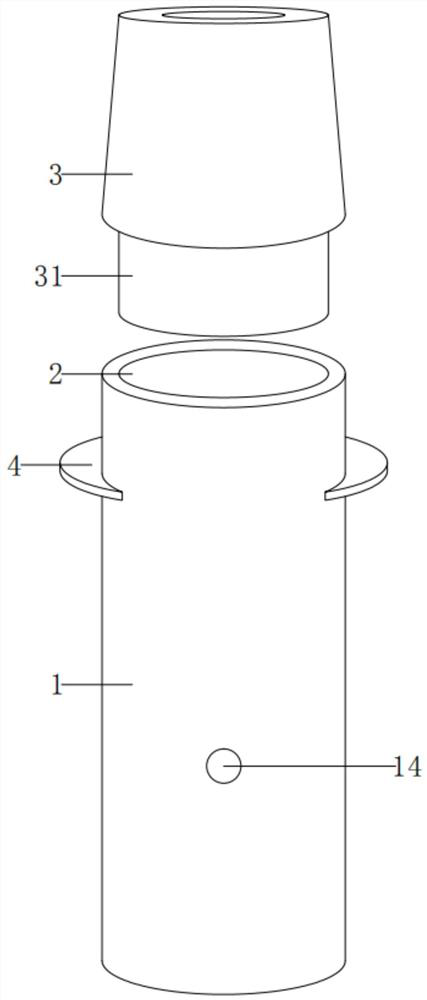
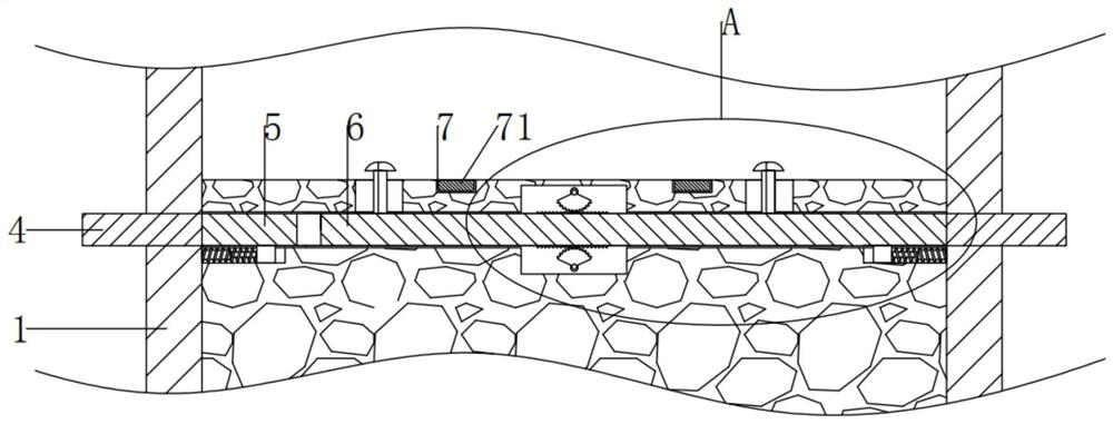
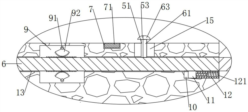
[0030] see Figure 1-7 , the present invention provides the following technical solutions:

[0031] A detachable electronic cigarette gun, comprising a cigarette rod 1 and a cartridge 3, the upper end of the cigarette rod 1 is dug with a cartridge groove 2, and the lower end of the cartridge 3 is fixed with an atomization plug 31, and the atomization plug 31 is movably plugged in In the pod slot 2, a chute 13 is cut at the left end of the pod 1, and a left slide 5 and a right slide 6 are movably inserted in the chute 13, the left slide 5 is in a "concave" shape, and the right slide 6 is movably inserted in the In the recess of the left skateboard 5, extrusion blocks 4 are respectively fixed on the far ends of the left skateboard 5 and the right skateboard 6, and the far ends of the two extrusion blocks 4 respectively penetrate the left and right ends of the cigarette rod 1 and extend toward both ends. Extending, the upper ends of the left slide plate 5 and the right slide pla...


PUM


Abstract

The invention provides a detachable electronic cigarette gun. The invention belongs to the technical field of electronic cigarettes; the detachable electronic cigarette gun comprises a cigarette rod and a cigarette cartridge; a cigarette cartridge groove is formed in the upper end of the cigarette rod; an atomization inserting block is fixed at the lower end of the cigarette cartridge; the atomization inserting block is movably inserted into the cigarette cartridge groove; a sliding groove is dug in the left end of the cigarette rod; a left sliding plate and a right sliding plate are movably inserted into the sliding groove. The left sliding plate is concave; the right sliding plate is movably inserted into the concave part of the left sliding plate; extrusion blocks are respectively fixedat the far ends of the left sliding plate and the right sliding plate; the far ends of the two extrusion blocks penetrate through the left end and the right end of the cigarette rod and extend towards the two ends. A plurality of first connecting blocks and second connecting blocks are respectively fixed at the upper ends of the left sliding plate and the right sliding plate; moreover, the plurality of first connection blocks and the plurality of second connection blocks are staggered respectively, and the upper ends of the plurality of first connection blocks are fixed with first card blocks; the device is simple in structure and convenient to disassemble, after the cigarette cartridge is used up, tobacco tar does not need to be added, the cigarette cartridge can be directly replaced, and operation is convenient and fast.

Description

technical field [0001] The invention belongs to the technical field of electronic cigarettes, and in particular relates to a detachable electronic cigarette gun. Background technique [0002] The idea that smoking is harmful to health has been deeply rooted in the hearts of the people, but it is still very difficult for most smokers to quit smoking. As an alternative cigarette product that is increasingly favored by consumers, electronic cigarettes generally do not contain tar, suspended particles and other harmful substances in cigarettes. The ingredients can also simulate the smoking process for the user and provide a real smoking experience. It is a substitute that can meet the body's demand for nicotine and has less harm. [0003] Existing electronic cigarettes generally consist of a cigarette rod and a pod, and the rod and the pod are fixedly connected. When one of the rod and the pod is damaged, they can only be replaced together, and it is not convenient to disassembl...

Claims


Application Information

Patent Timeline
Patent Type & Authority Applications(China)
IPC IPC(8): A24F40/10A24F40/42A24F40/40A24F40/46
CPCA24F40/10A24F40/40A24F40/42A24F40/46
Inventor 房蕊
Owner 苏州晨霞美合智能科技有限公司
Why Eureka
Eureka Blog
Learn More