

Combined detachable chair leg
A combination and chair foot technology, which is applied to chairs, other seating furniture, stools, etc., can solve the problems of cumbersome operation and low assembly efficiency, and achieve the effects of simplified assembly process, flexible and convenient use, and good load-bearing performance
- Summary
- Abstract
- Description
- Claims
- Application Information
AI Technical Summary
Problems solved by technology
Method used
Image

Examples
Embodiment 1
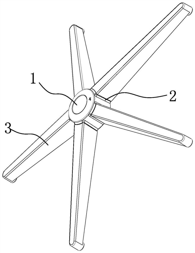
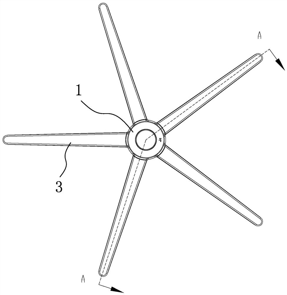
[0040] Such as figure 1 and figure 2 As shown, the combined detachable chair foot includes a center plate seat 1, and five single-leg connecting seats 2 that are evenly distributed around the circumference of the center plate seat 1 are connected. Further, the center plate seat 2 described in this embodiment The disc seat 1 and the single-leg connecting seat 2 are integrally formed by injection molding. Such as PA material and so on.
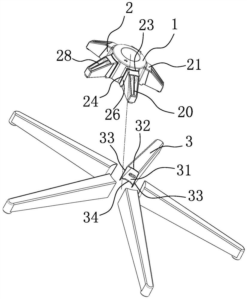
[0041] Secondly, if Figure 4 and Figure 5As shown, the lower surface of the center plate seat 1 is provided with a number of weight-reducing blind holes 10 evenly distributed around the circumference, and at least one weight-reducing blind hole is provided at the end of the lower surface of each single-leg connecting seat 2 near the center plate seat 1. Kong II 27. Blind holes for weight reduction can save materials and reduce manufacturing costs.
[0042] Such as image 3 and Figure 6 As shown, the upper surface of each single-leg c...
Embodiment 2
[0067] The working principle and structure of this embodiment are basically the same as those of Embodiment 1. The different structure is that the outer axial concave-convex locking structure includes a locking hole arranged on the lower surface of the single-leg connecting seat 2 away from the end of the middle disc seat 1. 37. An upwardly protruding lower locking projection 29 is provided at the inner end of the lower side of the flip assembly single foot 3, and when the flip assembly single foot 3 is turned upward and in place, the lower locking projection 29 is inserted into the lock In the stop hole 37, an L-shaped buckling surface 290 is provided on the side of the lower locking protrusion 29 in the circumferential direction close to the center plate seat 1, and the L-shaped buckling surface 290 is buckled when the single leg 3 is flipped upwards and put in place. Fitted on the hole wall of the locking hole 37 near the side of the middle disc seat 1, the side of the lower...
Embodiment 3
[0069] The working principle and structure of this embodiment are basically the same as those of Embodiment 1, the difference in structure is: the matching slope 1 21 of this embodiment is an inclined plane, and the matching slope 2 30 is an inclination matching with the matching slope 1 21 flat.
PUM
 Abstract
Description
Claims
Application Information