Centrifugal separation device

A centrifugal separation and shell technology, which is applied in separation methods, dispersed particle separation, chemical instruments and methods, etc., can solve the problem of low removal efficiency of small particle size particles, and achieve the effect of improving dust removal efficiency and speeding up the movement speed

Pending Publication Date: 2020-09-08
中国人民解放军火箭军工程大学
View PDF0 Cites 0 Cited by
  • Summary
  • Abstract
  • Description
  • Claims
  • Application Information

AI Technical Summary

Problems solved by technology

[0003] The purpose of this application is to provide a centrifugal separation device to improve the techn

Method used


Image

  • Centrifugal separation device
  • Centrifugal separation device
  • Centrifugal separation device

Examples


Example Embodiment

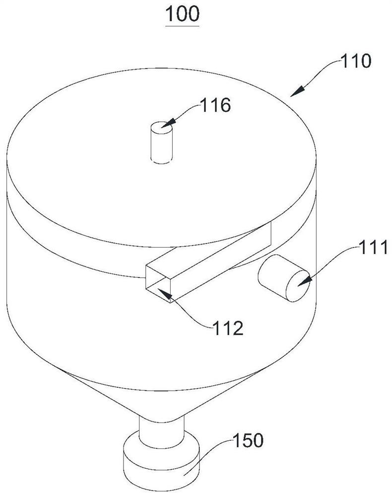
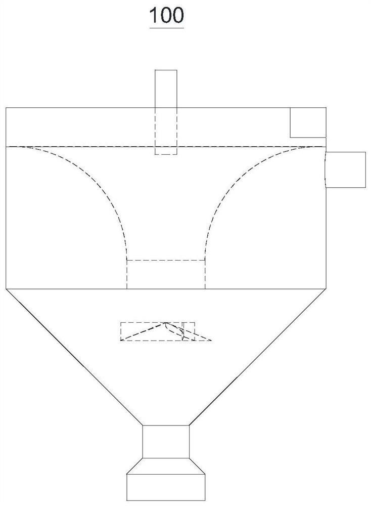
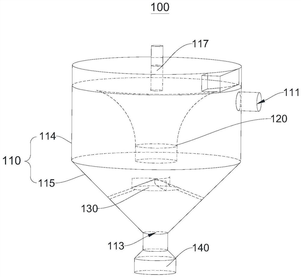
[0026] In order to make the purposes, technical solutions and advantages of the embodiments of the present application clearer, the technical solutions in the embodiments of the present application will be described clearly and completely below with reference to the drawings in the embodiments of the present application. Obviously, the described embodiments It is a part of the embodiments of the present application, but not all of the embodiments. The components of the embodiments of the present application generally described and illustrated in the drawings herein may be arranged and designed in a variety of different configurations. Thus, the following detailed description of the embodiments of the application provided in the accompanying drawings is not intended to limit the scope of the application as claimed, but is merely representative of selected embodiments of the application. Based on the embodiments in the present application, all other embodiments obtained by those...


PUM


Abstract

The invention provides a centrifugal separation device, and relates to the technical field of centrifugal separation devices. The centrifugal separation device comprises a shell, a shrinkage pipe anda conical cap, wherein the shrinkage pipe is located in the shell, the flaring end of the shrinkage pipe is located between an air outlet and an air inlet, the circumferential edge of the flaring endof the shrinkage pipe is connected with the side wall in a sealed mode, the closing end of the shrinkage pipe extends to the position near the second end of the shell, the conical cap is suspended inthe shell and located between the closing end of the shrinkage pipe and the second end of the shell, a gap allowing particles to pass through is reserved between the conical cap and the side wall, thetip end of the conical cap points to the closing end of the shrinkage pipe, and a plurality of blades are arranged on the surface, facing the shrinkage pipe, of the conical cap. According to the invention, the conical cap is arranged in the shell, and the blades are arranged on the conical cap, so that the rotation of gas is promoted, the centrifugal force is increased, the dust removal efficiency is improved, and tiny particles in the gas are separated and removed.

Description

technical field [0001] The present application relates to the technical field of centrifugal separation devices, in particular, to centrifugal separation devices. Background technique [0002] In the field of dust removal, cyclone separator is an industrial dust removal system with simple structure and stable operation, which has a significant effect on the removal of particles in dusty gas. Cyclone separators can be used alone or as pretreatment equipment for other dust removal systems. As a separate dust removal system, the cyclone separator has a low removal efficiency for particles with small particle sizes. When it is operated in conjunction with other dust removal systems, the equipment system is relatively large and occupies a large area. Contents of the invention [0003] The purpose of this application is to provide a centrifugal separation device to improve the technical problem of low removal efficiency of small particle size particles by a separate dust remova...

Claims


Application Information

Patent Timeline
IPC IPC(8): B01D45/16
CPCB01D45/16
Inventor 贾瑛侯立安王博王厚成刘渊吕晓猛沈可可
Owner 中国人民解放军火箭军工程大学
Why Eureka
Try Eureka