Intelligent inspection robot

An intelligent inspection and robot technology, applied in the direction of manipulators, program-controlled manipulators, manufacturing tools, etc., can solve the problem of large errors in the angle and orientation of the collected images, the inability to accurately correspond to the positional relationship of inspection points or coordinate inspection data, and the inability to meet precise Requirements and other issues to achieve or reduce errors, accurately correspond to positional relationships, and avoid errors

Pending Publication Date: 2020-09-08
吴洪婷
View PDF10 Cites 12 Cited by
  • Summary
  • Abstract
  • Description
  • Claims
  • Application Information

AI Technical Summary

Problems solved by technology

However, the current inspection robot cannot move horizontally throughout the entire process in an ideal state because the inspection road is not completely flat, and there are special situations such as uphill and downhill.
However, when the camera adopts a fixed shooting pose throughout the entire path, there are large errors in the angle and orientation of the captured image, which cannot meet the requirements when constructing a panorama stitching (that is, splicing sub-pictures of several small viewing angle areas into a general panorama image). Accurate requirements for the angle and orientation of each sub-image, and at the same time, it is impossible to accurately correspond to the positional relationship between the inspection points or coordinate inspection data and the overall panorama

Method used


Image

  • Intelligent inspection robot
  • Intelligent inspection robot
  • Intelligent inspection robot

Examples


Embodiment 1

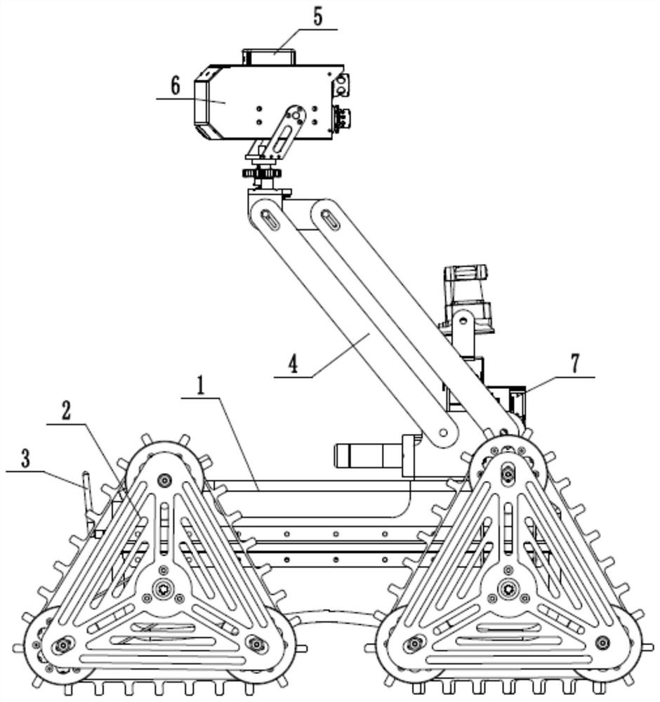
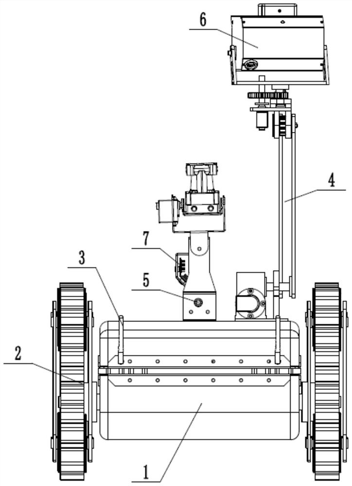
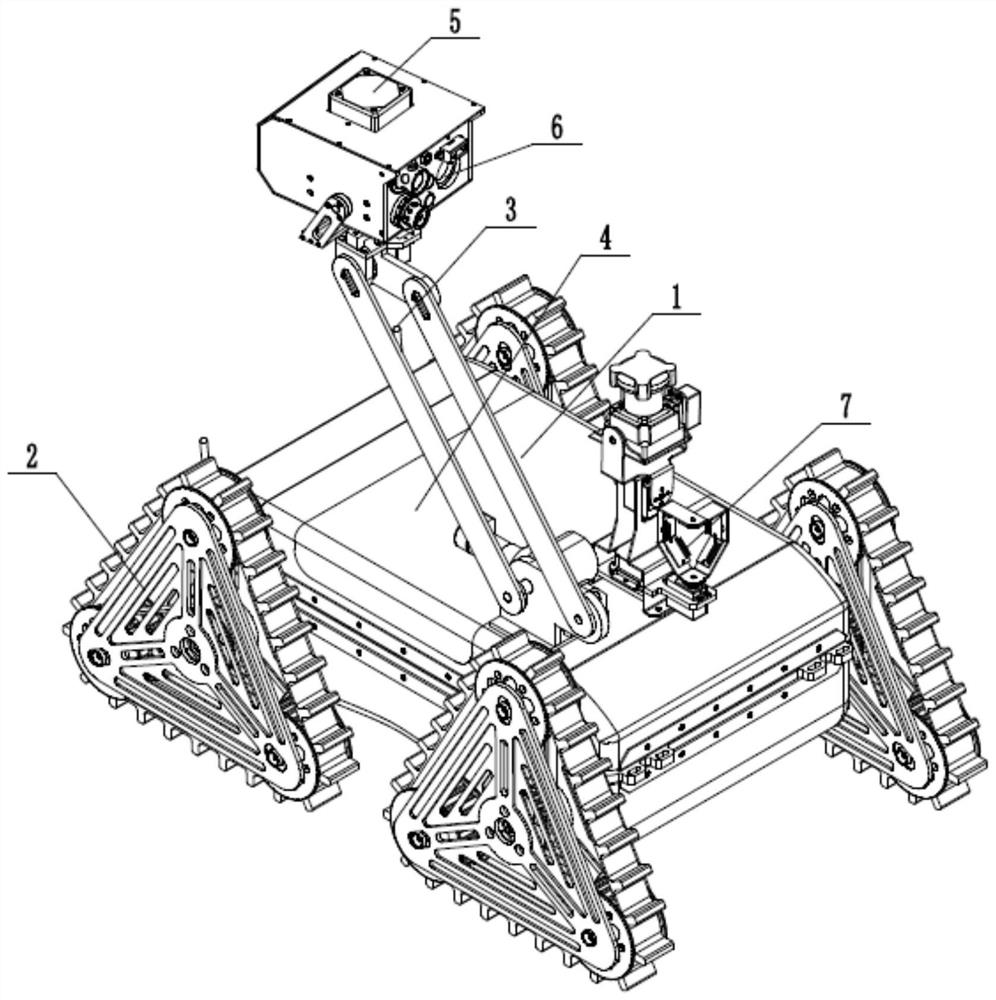
[0033] Embodiment one: see Figure 1-11 , an intelligent inspection robot, which includes a vehicle body 1, a walking mechanism 2, an AGV navigation unit 3, a pose adjustment mechanism 4, a pose detection unit 5, an image acquisition unit 6, an inspection data acquisition unit 7 and a controller.

[0034] The traveling mechanism is arranged on the vehicle body and is used to drive the vehicle body to walk. Preferably, the running mechanism includes a crawler mechanism and a steering mechanism. The steering mechanism and the crawler movement mechanism are respectively controlled by different motors, so that the speed and steering of the adjustment movement, as well as the movement modes such as forward and backward can be realized.

[0035] In addition, the running mechanism can be the same as that of the existing AGV trolley.

[0036] In addition, a storage battery is provided inside the vehicle body to provide power.

[0037] The AGV navigation unit is used to guide the ro...

Embodiment 2

[0066] Embodiment two: see Figure 10-11 , a working method that includes:

[0067] S1, set the inspection route of the robot, and set a number of inspection points on the inspection route, each inspection point corresponds to a standard shooting pose when an image acquisition unit collects images, and establish a number of inspection points and images A database of several standard shooting pose correspondences when the acquisition unit acquires images;

[0068] For example, when inspecting a group of substations in a certain area, first preset the inspection route of the robot, that is, preset the walking guide route data of the robot; Adopt at each parking inspection point to set identification mark), and these 5 parking inspection points can take the view pictures of 5 inspection areas respectively; Then set the angle of the CCD camera when 5 parking inspection points are photographed, The direction and height are used as the standard shooting pose when the image acquisi...


PUM


Abstract

The invention discloses an intelligent inspection robot. The intelligent inspection robot is characterized by comprising a vehicle body, a walking mechanism, an AGV navigation unit, a pose adjusting mechanism, a pose detecting unit, an image acquiring unit, an inspection data acquiring unit and a controller, wherein the AGV navigation unit is used for guiding the robot to walk along an inspectionroute; the image acquiring unit is used for acquiring image information; the pose detecting unit is used for acquiring shooting pose information in sequence and sending the shooting pose information to the controller; the pose adjusting mechanism is used for adjusting the shooting pose information of the image acquiring unit; and the inspection data acquiring unit is used for acquiring inspectiondata information of multiple inspection points on the inspection route in sequence. The intelligent inspection robot can automatically adjust the pose of a camera during shooting according to specialroad conditions during inspection to reduce large image acquiring angle and direction errors so as to satisfy the precise requirements of panoramic splicing construction.

Description

technical field [0001] The invention relates to an intelligent inspection robot and a working method. Background technique [0002] Inspection robots are used to complete disasters, high-risk environments (power grids, production workshops, chemical plants, etc.), specific area inspections, etc., which can reduce the workload, reduce the safety risks of operators, replace heavy manual inspections, and improve inspection Intelligent automation and reduce labor costs. However, the current inspection robot cannot move horizontally throughout the entire process in an ideal state because the inspection road is not completely flat, and there are special situations such as uphill and downhill. However, when the camera adopts a fixed shooting pose throughout the entire path, there are large errors in the angle and orientation of the captured image, which cannot meet the requirements when constructing a panorama stitching (that is, splicing sub-pictures of several small viewing angl...

Claims


Application Information

Patent Timeline
Patent Type & Authority Applications(China)
IPC IPC(8): B25J11/00B25J9/16B25J5/00B25J19/02
CPCB25J11/00B25J5/005B25J9/1697B25J19/023
Inventor 吴洪婷
Owner 吴洪婷
Why Eureka
Try Eureka