Split wire arrangement device for communication optical fiber cables and use method thereof

A communication optical cable and wiring device technology, which is applied in the field of split wiring devices for communication optical cables, can solve the problems of optical cables falling on the ground, affecting the service life of optical cables, and affecting the wiring efficiency of optical cables, so as to reduce the number of uses and improve wiring efficiency. Ease of movement

Inactive Publication Date: 2020-09-08
广州鑫源网络科技有限公司
View PDF23 Cites 0 Cited by
  • Summary
  • Abstract
  • Description
  • Claims
  • Application Information

AI Technical Summary

Problems solved by technology

[0003] Most of the existing wiring devices for communication optical cables can only support and fix a roll of optical cables when they are in use. However, the number of optical cables used in on-site wiring is large, and multiple devices are required for support, which makes the on-site wiring confusing and affects installation efficiency. , secondly, the supporting height of the existing communication optical cable wiring device is relatively low, and it is easy to cause the optical cable to fall on the ground, thereby generating friction, causing damage to the surface of the optical cable, and affecting the service life of the optical cable. , the frictional resistance is large, the transportation is inconvenient, affects the efficiency of optical cable wiring, and has low practicability. Therefore, a split wiring device for communication optical cables is needed to solve the existing problems.

Method used


Image

  • Split wire arrangement device for communication optical fiber cables and use method thereof
  • Split wire arrangement device for communication optical fiber cables and use method thereof
  • Split wire arrangement device for communication optical fiber cables and use method thereof

Examples


Embodiment Construction

[0033] The present invention will be further explained below in conjunction with the drawings:

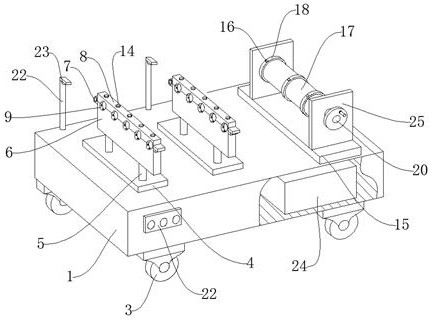
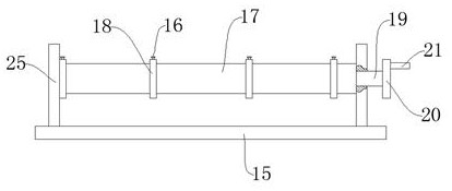
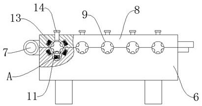
[0034] Such as Figure 1-Figure 4 As shown, a split wiring device for a communication optical cable includes a base 1, a supporting base 15 and a reel 17, the upper side of the base 1 is connected to the supporting base 15 by bolts, the supporting base 15 Both sides of the upper end are connected by bolts with support frames 25, the reel 17 is rotatably connected between the support frames 25, the reel 17 is slidably connected to a limit ring 18, and the limit ring 18 is connected by threads There are two fixing bolts 16. One side of the support frame 25 is connected with a connecting shaft 19 through a bearing. The connecting shaft 19 is connected with the reel 17 through a screw thread. One end of the connecting shaft 19 is connected with a runner 20 through a bolt. A rotating handle 21 is connected to one side of the rotating wheel 20 by bolts, and the communication optical cable ...


PUM


Abstract

The invention discloses a split wire arrangement device for communication optical fiber cables and a use method thereof. The split wire arrangement device comprises a base, a second supporting seat and a drum. One side of the upper end of the base is connected with the second supporting seat through a bolt, and the two ends of the upper end of the second supporting seat are connected with supporting frames through bolts. The drum is rotationally connected between the supporting frames. The drum is in slidably connected with a limiting ring, and the limiting ring is connected with a second fixed bolt through a thread. The split wire arrangement device has the advantages that the structure is novel and operation is convenient; the second supporting seat, the supporting frames, the drum, thelimiting ring and the second fixed bolt are arranged, and therefore the communication optical fiber cables can be effectively supported and fixed, multiple coils of communication optical fiber cablescan be placed on the drum, the capacity is large, and the use needs are met; and therefore the number of adopted devices can be reduced, the cleanliness of a mounting field is guaranteed, and the mounting efficiency is improved.

Description

Technical field [0001] The invention relates to the technical field of communication optical cable wiring devices, in particular to a split wiring device for communication optical cables and a method of use thereof. Background technique [0002] Communication optical cable is composed of a cable core and outer sheath composed of several optical fibers. It is a communication line used to realize optical signal transmission. Compared with the traditional symmetrical copper circuit and coaxial copper circuit, the optical fiber has a large transmission capacity. More, less attenuation, long transmission distance, small size, light weight, no electromagnetic interference, and low cost. It is currently the most promising communication transmission medium. It is widely used for signal transmission in various sectors such as telecommunications, electric power, and broadcasting. It will gradually become the main body of the future communication network. [0003] However, most of the existi...

Claims


Application Information

Patent Timeline
Patent Type & Authority Applications(China)
IPC IPC(8): B65H75/44B65H57/06B65H57/16
CPCB65H57/06B65H57/16B65H75/4492B65H2701/32
Inventor 张伟超
Owner 广州鑫源网络科技有限公司
Why Eureka
Try Eureka