Multi-supporting post anti-floating box body for cast-in-place concrete hollow floor slab
- Summary
- Abstract
- Description
- Claims
- Application Information
AI Technical Summary
Problems solved by technology
Method used
Image

Examples
Embodiment Construction
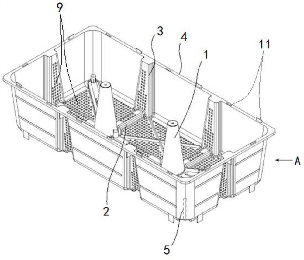
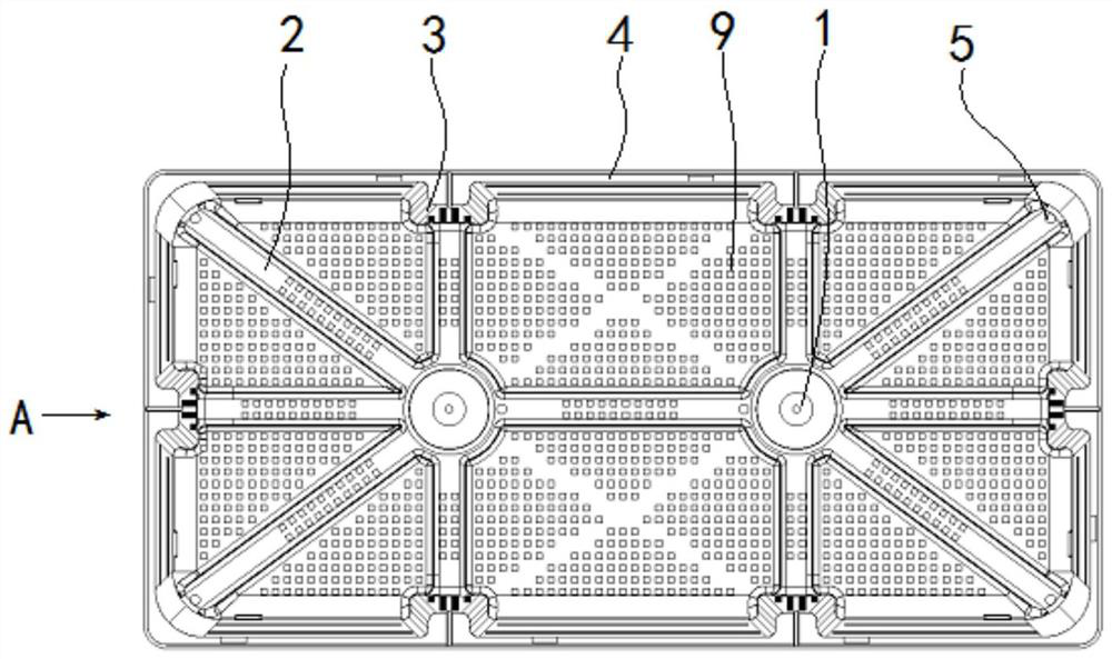
[0027] attached by figure 1 , 2 As shown: the multi-pillar anti-floating tank includes a tank body A, which is characterized in that: the tank body A is a cubic groove structure, and at least two pillars 1 perpendicular to the bottom surface are evenly distributed inside the tank body A , the bottom surface of the box body A is processed with rice-shaped reinforcing ribs 2 with vent holes 9, and vent holes 9 are evenly distributed between the reinforcing ribs on the bottom surface of the box body A, and the four sides of the box body A Vertical ribs 3 with air vents 9 are processed on each side, the upper end of the side of the box body A has a circumferential fixed edge 4, and the four corners of the box body A are vertically processed with supports Leg mounting holes 5.
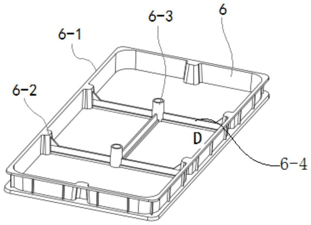
[0028] attached by image 3 As shown: the multi-pillar anti-floating tank also includes a tank heightening section D6, which is arranged on the end face of the tank body during assembly, and the box body...
PUM
 Abstract
Description
Claims
Application Information