
A numerically controlled blower fan for easy adjustment of wind gear

A fan and gear technology, which is applied to the components of the pumping device for elastic fluids, mechanical equipment, machines/engines, etc. Mobility, improved ventilation effect, the effect of changing the workplace

Active Publication Date: 2021-09-24
安徽庐风风机有限公司
View PDF10 Cites 0 Cited by
  • Summary
  • Abstract
  • Description
  • Claims
  • Application Information

AI Technical Summary

Problems solved by technology

[0004] The purpose of the present invention is to provide a numerically controlled fan that is easy to adjust the wind power gear to solve the above-mentioned background technology. Convenient location, according to the Chinese patent (CN201720549579.6) a fan that is easy to adjust the wind force quickly, the device adjusts the wind force by changing the area of ​​the fan blades, and by setting the first block and the second block, more Well, through the cooperation of the first meshing teeth and the second meshing teeth, it is convenient to adjust the area of ​​the first fan blade and the second fan blade, so as to adjust the wind force. By setting the conical shaft with grooves, it is convenient Push the first block smoothly, and adjust the first block and the second block better by setting the first screw and the second screw, so as to facilitate the adjustment of the size of the fan blades, so as to facilitate the adjustment of the wind force , and the structure is simple, the design is reasonable, the operation is convenient, safe and reliable, but the device is not equipped with a driveable rotation structure, so that the overall wind outlet angle of the fan cannot be changed, and the wind outlet angle can only be changed by changing the overall angle of the fan. poor functionality

Method used


Image

  • A numerically controlled blower fan for easy adjustment of wind gear
  • A numerically controlled blower fan for easy adjustment of wind gear
  • A numerically controlled blower fan for easy adjustment of wind gear

Examples


Embodiment Construction

[0026] The technical solution of this patent will be further described in detail below in conjunction with specific embodiments.

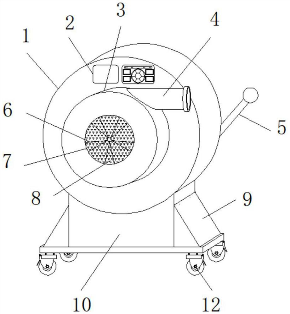
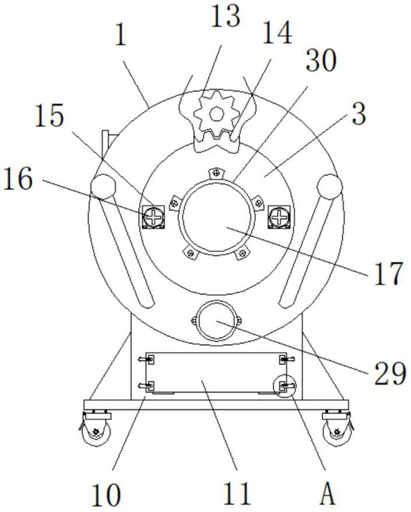
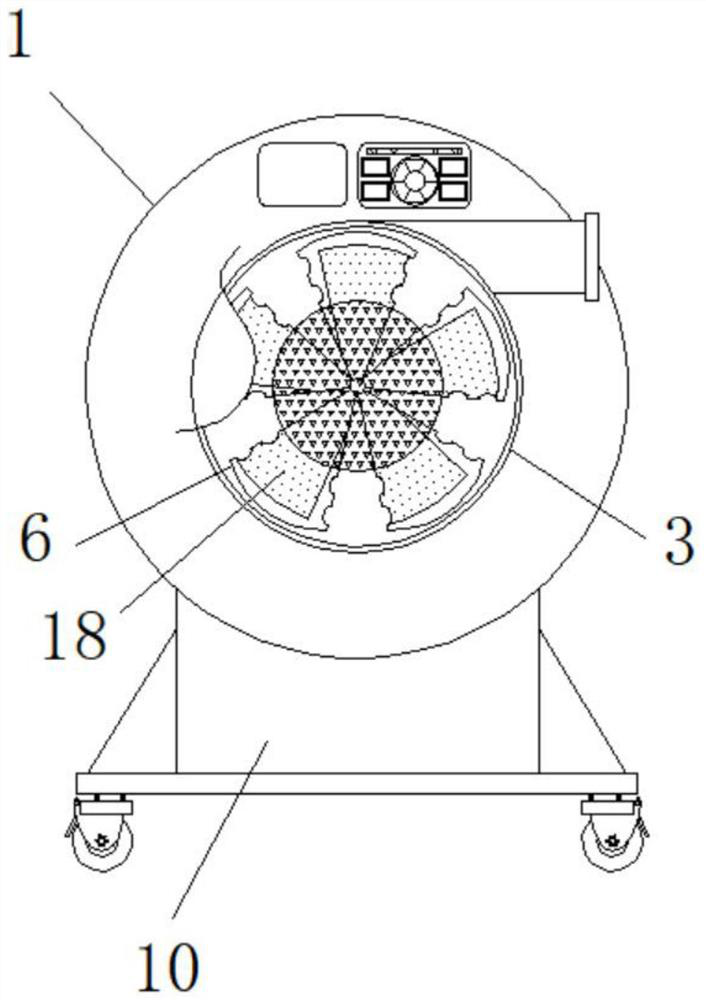
[0027] see Figure 1-6 , a numerically controlled fan for easy adjustment of the wind gear, including a mounting shell 1, a fan sleeve 3, a fan blade 6, a mounting seat 10, a driving motor 17, a displacement-proof support base plate 20 and a driving motor 29, the mounting shell 1 A mounting seat 10 is fixedly installed at the bottom, a digital display screen 2 is inlaid on the front outer wall of the mounting shell 1, and a fan sleeve 3 is mounted on the inner rotation of the mounting shell 1, and a fan sleeve 3 is installed on the back outer wall of the fan sleeve 3. The driving motor 17 is fixedly installed by installing the fixing ring 30, the output end of the driving motor 17 is equipped with a rotating shaft, and one end of the rotating shaft passes through and extends to the inside of the fan sleeve 3. The fan blade 6 is fixedly installed, a...


PUM


Abstract

The invention discloses a numerically controlled fan that is convenient for adjusting the wind power gear, and relates to the field of numerically controlled fans, including a mounting shell, a fan sleeve, a fan blade, a mounting seat, a driving motor, a displacement-preventing support base plate and a driving motor. The bottom is fixedly installed with an installation seat, the front outer wall of the installation shell is inlaid with a digital display screen, and the inside of the installation shell is rotatably installed with a fan sleeve, and the rear outer wall of the fan sleeve is fixed and installed by installing a fixing ring There is a drive motor; the invention installs a rotatable fan sleeve, and when it is necessary to change the wind outlet angle of the fan, it does not need to move the whole fan device, and directly rotates the fan sleeve to quickly change the wind outlet angle of the fan. It is easy to adjust, and the driving gear is installed inside the fan, and the movable meshing teeth are regularly installed on the outside of the fan sleeve, through the gear meshing transmission, the fan sleeve can be rotated at a uniform speed when changing the angle, and the gear transmission is stable. higher.

Description

technical field [0001] The invention belongs to the field of numerically controlled blowers, in particular to a numerically controlled blower which is convenient for adjusting wind gears. Background technique [0002] A fan is a machine that relies on input mechanical energy to increase gas pressure and discharge gas. It is a driven fluid machine. Fan is the customary abbreviation for gas compression and gas conveying machinery in China. There are many types of fans. Generally speaking, fans include ventilators, blowers, and wind generators. Fans are widely used in factories, mines, tunnels, cooling towers, Ventilation, dust extraction and cooling of vehicles, ships and buildings, ventilation and induction of boilers and industrial furnaces; cooling and ventilation in air conditioning equipment and household appliances; drying and sorting of grain, wind tunnel wind source and The role of fans in machinery is self-evident for the inflation and propulsion of hovercraft. [0...

Claims


Application Information

Patent Timeline
Patent Type & Authority Patents(China)
IPC IPC(8): F04D25/08F04D29/00F04D29/42F04D29/46F04D29/70
CPCF04D25/08F04D29/002F04D29/4226F04D29/462F04D29/703
Inventor 傅强杨从贵管照正彭拥军王晓松周玉红徐经存
Owner 安徽庐风风机有限公司
Learn More