
Centrifugal fan capable of controlling air blowing direction

A centrifugal fan and blower technology, applied in pump control, mechanical equipment, radial flow pump, etc., can solve problems such as loud noise and air backflow

Inactive Publication Date: 2020-12-22
江西艾威尔压缩机有限公司
View PDF10 Cites 0 Cited by
  • Summary
  • Abstract
  • Description
  • Claims
  • Application Information

AI Technical Summary

Problems solved by technology

[0004] The purpose of the present invention is to provide a centrifugal fan with controllable blowing direction to solve the problems in the above-mentioned background art that the centrifugal fan will generate a lot of noise and the air inhaled by the centrifugal fan will flow back inside the machine body.

Method used


Image

  • Centrifugal fan capable of controlling air blowing direction
  • Centrifugal fan capable of controlling air blowing direction
  • Centrifugal fan capable of controlling air blowing direction

Examples


Embodiment Construction

[0025] The following will clearly and completely describe the technical solutions in the embodiments of the present invention with reference to the accompanying drawings in the embodiments of the present invention. Obviously, the described embodiments are only some, not all, embodiments of the present invention. Based on the embodiments of the present invention, all other embodiments obtained by persons of ordinary skill in the art without making creative efforts belong to the protection scope of the present invention.

[0026] In the present invention, unless otherwise clearly specified and limited, the terms "set", "install", "connect", "connect", "fix", "socket", and other terms should be understood in a broad sense, for example, It can be a fixed connection, or it can be a detachable connection, or integrated; it can be a mechanical connection, or it can be an electrical connection; it can be directly connected, or indirectly connected through an intermediary, and it can be...


PUM


Abstract

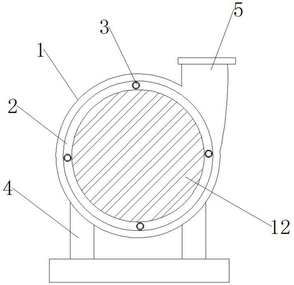
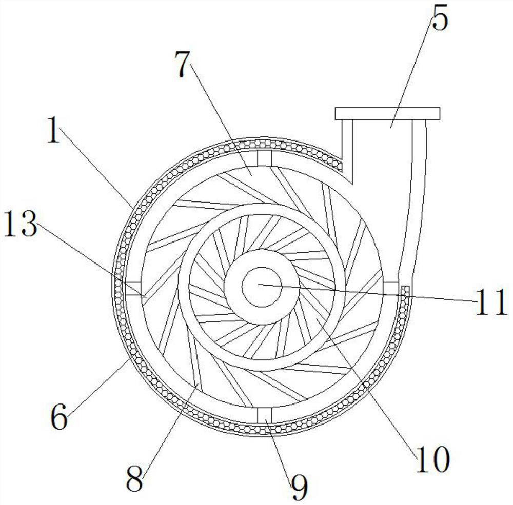
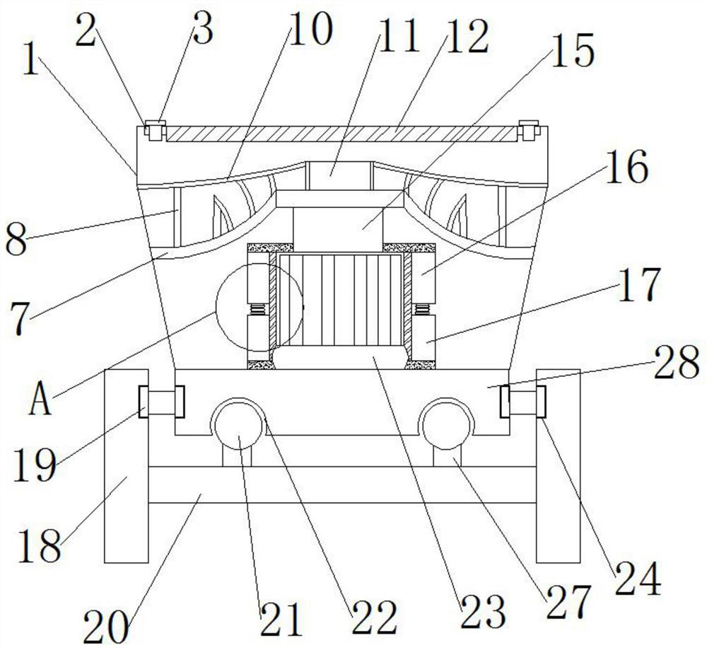
The invention discloses a centrifugal fan capable of controlling air blowing direction, and relates to the technical field of centrifugal fans. The centrifugal fan capable of controlling the air blowing direction comprises a casing, a frame is mounted at the top of the casing, an air deflector is mounted at the top of the frame, the two sides of the top of the frame are connected with the casing through fixing shafts, an air inlet frame is mounted on one side of the outer surface of the casing, and a supporting frame is connected to the back of the casing. According to the centrifugal fan capable of controlling the air blowing direction, through a first impeller, a second impeller and the air deflector, the fan is started to start the whole centrifugal fan; the centrifugal fan sucks wind power into the casing through the air inlet frame; when the wind power enters the casing, an air outlet passage is formed through inclined blades of the second impeller and inclined blades of the firstimpeller; when air passes through the gap of the air outlet passages formed by the inclined blades of the second impeller and the inclined blades of the first impeller, a certain initial speed pointing to an air outlet is obtained, so that the rotation direction of the wind power in the casing is consistent; and therefore, the backflow situation cannot be generated.

Description

technical field [0001] The invention relates to the technical field of centrifugal fans, in particular to a centrifugal fan with controllable blowing direction. Background technique [0002] The centrifugal fan is a machine that relies on the input mechanical energy to increase the gas pressure and discharge the gas. It is a driven fluid machine. The centrifugal fan is widely used in the ventilation of factories, mines, tunnels, cooling towers, vehicles, ships and buildings. Dust extraction and cooling; ventilation and induction of boilers and industrial furnaces; cooling and ventilation in air conditioning equipment and household electrical appliances; drying and selection of grain; wind tunnel wind source and inflation and propulsion of hovercraft, etc., centrifugal fan According to the principle of converting kinetic energy into potential energy, the high-speed rotating impeller is used to accelerate the gas, then decelerate and change the flow direction, so that the kine...

Claims


Application Information

Patent Timeline
IPC IPC(8): F04D17/16F04D25/08F04D29/44F04D29/42F04D29/28F04D29/30F04D29/66F04D29/62F04D27/00
CPCF04D17/16F04D25/08F04D29/441F04D29/4206F04D29/4226F04D29/283F04D29/30F04D29/663F04D29/667F04D29/668F04D29/626F04D27/002
Inventor 丁汝秋
Owner 江西艾威尔压缩机有限公司
Learn More