
A protective cooling air conditioning device

A technology of air conditioning and outer box, which is applied to pump devices, parts of pumping devices for elastic fluids, furnaces, etc. It can solve the problems of poor cooling capacity of furnace fans and reduce the service life of fans, and avoid temperature rise High, improve the safety level, easy to clean the effect

Active Publication Date: 2021-11-12
南通南洋风机制造有限公司
View PDF6 Cites 0 Cited by
  • Summary
  • Abstract
  • Description
  • Claims
  • Application Information

AI Technical Summary

Problems solved by technology

[0005] Aiming at the deficiencies of the prior art, the present invention provides a protective cooling air conditioning device, which solves the problem of poor cooling ability of the existing furnace fan, and can avoid the use of the fan around the high-temperature furnace for a long time when the temperature is too high to reduce the use of the fan Long life, can clean the dust on the surface of the fan, improve the cleanliness of the fan, reduce the difficulty of cleaning inside the device, and can concentrate and facilitate the cleaning of the dust inside the device

Method used

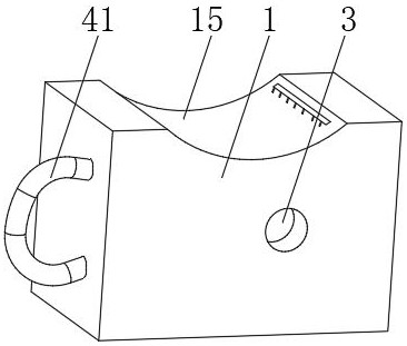

Image

  • A protective cooling air conditioning device
  • A protective cooling air conditioning device
  • A protective cooling air conditioning device

Examples


Embodiment 1

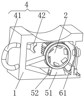
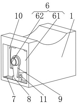
[0034] see Figure 1-3 , the present invention provides a technical solution: a protective cooling air conditioning device, including an outer box 1, a fan main body 2 is installed inside the outer box 1, an air outlet is opened on one side of the outer box 1, and one side of the outer box 1 An air inlet 3 is provided near the main body of the fan 2, and the air inlet 3 runs through the outer box 1 and the main body of the fan 2, and the interior of the outer box 1 is provided with:

[0035] Cooling device 4, the cooling device 4 has an air outlet pipe 41, the air outlet pipe 41 communicates with the air outlet of the fan main body 2, one end of the air outlet pipe 41 runs through the outer box 1 and extends to the top of the fan main body 2, the air outlet pipe 41 The end away from the main body of the fan 2 is connected with a diffuser hood 42;

[0036] The guide device 6 , the guide device 6 has a windshield film 61 , a guide tube 62 is installed on one side of the windshi...

Embodiment 2

[0045] see Figure 1-5 , the present invention provides a technical solution: on the basis of Embodiment 1, a dust collection device 5 is provided inside the outer box 1, the dust collection device 5 has a support block 51, and the support block 51 is installed on the inner bottom of the outer box 1, Fan main body 2 is installed on the top of support block 51, and support block 51 is provided with dust collection groove 52 near the side of wind diffuser cover 42, and the bottom of dust collection groove 52 runs through support block 51 and outer case 1, and the inner wall of dust collection groove 52 A dust box 53 is slidably connected between the two sides, and an elastic rope 54 is fixedly connected to the top of the dust box 53 .

[0046] One side of the inner wall of the dust box 53 is rotatably connected with a swing plate 12 , the bottom of the swing plate 12 is fixedly connected with a tension spring 13 , and the end of the tension spring 13 away from the swing plate 12...


PUM


Abstract

The invention discloses a protective and cooling air conditioner, which comprises an outer box, a fan main body is installed inside the outer box, an air outlet is opened on one side of the outer box, and one side of the outer box is close to the side of the fan main body. An air inlet is provided at the position, and the air inlet runs through the outer box and the main body of the fan, and the inside of the outer box is provided with: a cooling device, the cooling device has an air outlet pipe, and the air outlet pipe communicates with the air outlet of the fan main body; A dust collection device, the dust collection device has a support block; a guide device, the guide device has a windshield membrane, and the invention relates to the technical field of fans. The protective cooling air conditioning device achieves the purpose of improving the cooling capacity, and can avoid prolonged use around the high-temperature furnace and reduce the service life of the fan. It can clean the dust on the surface of the fan, improve the cleanliness of the fan, and reduce the It is difficult to clean the inside of the device, and the dust inside the device can be concentrated and conveniently cleaned.

Description

technical field [0001] The invention relates to the technical field of fans, in particular to a protective cooling air conditioning device. Background technique [0002] In recent years, with the rapid development of the national economy, the non-ferrous metal processing industry represented by the aluminum industry has achieved rapid development, and the non-ferrous metal processing equipment industry has also developed greatly, especially heating furnaces, annealing furnaces, Heat treatment equipment such as soaking furnaces and aging furnaces are developing rapidly. Fans are installed in existing heat treatment equipment such as industrial furnaces. With the increase in the processing capacity of industrial furnaces, they are especially used for carbon car bottom roasters. [0003] However, the cooling capacity of the existing furnace fan is relatively poor, and the service life of the fan is likely to be reduced if the temperature is too high around the high-temperature ...

Claims


Application Information

Patent Timeline
Patent Type & Authority Patents(China)
IPC IPC(8): F04D25/08F04D29/42F04D29/44F04D29/70F27D9/00
CPCF04D25/08F04D29/4226F04D29/441F04D29/703F27D9/00F27D2009/0005
Inventor 吴南华
Owner 南通南洋风机制造有限公司
Learn More