
Digital electromagnetic pen, input system and control method thereof

An electromagnetic pen, digital technology, applied in the input/output process of data processing, electrical digital data processing, digital data processing components and other directions, can solve the problems affecting pressure and coordinate stability, large power consumption, and long power supply problems such as time and counting, to achieve the effect of circuit saving, fast speed and high flexibility

Pending Publication Date: 2020-09-08
SHENZHEN HUION ANIMATION TECH
View PDF4 Cites 1 Cited by
  • Summary
  • Abstract
  • Description
  • Claims
  • Application Information

AI Technical Summary

Problems solved by technology

The passive electromagnetic pen is divided into analog type and digital type. The analog type transmits key and pressure signals to the tablet by changing the frequency or phase, such as the US patent US5600105. Therefore, a large bandwidth is required to cover the frequency range, which is easy to let Unexpected frequency (noise) affects the stability of the pressure and coordinates. The digital type uses the fixed-frequency amplitude modulation mode to transmit the key and pressure signals to the digital board, such as US patents US5969296 and US5977959, so it requires a longer power supply time and Only counting can take a higher pressure order, which consumes a lot of power

Method used


Image

  • Digital electromagnetic pen, input system and control method thereof
  • Digital electromagnetic pen, input system and control method thereof
  • Digital electromagnetic pen, input system and control method thereof

Examples


Embodiment Construction

[0057] The technical solutions in the embodiments of the present invention will be clearly and completely described below with reference to the drawings in the embodiments of the present invention. Obviously, the described embodiments are only a part of the embodiments of the present invention, but not all of the embodiments. Based on the embodiments of the present invention, all other embodiments obtained by those of ordinary skill in the art without creative efforts shall fall within the protection scope of the present invention.

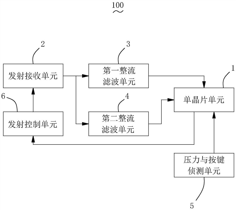
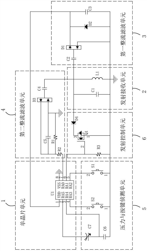
[0058] see figure figure 1 , is a structural block diagram of the digital electromagnetic pen provided by the present invention. The present invention provides a digital electromagnetic pen 100, which includes a single chip unit 1, a transmitting and receiving unit 2, a first rectifying and filtering unit 3, and a second rectifying and filtering unit 4. , pressure and key detection unit 5 and emission control unit 6 . The single-chip unit 1 , the...


PUM


Abstract

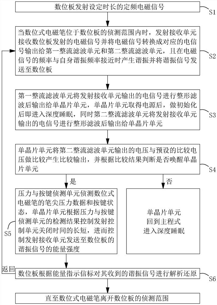
The invention provides a digital electromagnetic pen. The digital electromagnetic pen comprises a single-chip microcomputer unit, an emission control unit and an emission receiving unit, wherein the single-chip microcomputer unit, the emission control unit and the emission receiving unit are connected in sequence. A first rectifying and filtering unit and a second rectifying and filtering unit areconnected between the single-chip microcomputer unit and the emission receiving unit in parallel. A pressure and key detection unit is connected with the single-chip microcomputer unit. The emissionreceiving unit receives the electromagnetic signals transmitted by the digital panel, converts the electromagnetic signals into corresponding electric signals and outputs the electric signals to the first rectifying and filtering unit and the second rectifying and filtering unit. The first rectifying and filtering unit performs shaping and filtering on the electric signal and outputs the electricsignal to the single-chip microcomputer unit; the second rectifying and filtering unit performs shaping and filtering on the electric signal and then outputs the electric signal to the single-chip microcomputer unit to wake up the single-chip microcomputer unit. The pressure and key detection unit is used for detecting nib pressure data and a key state. The single-chip microcomputer unit controlsthe closing time of the emission control unit according to the detection result. Meanwhile, the invention further provides an input system and a control method thereof.

Description

technical field [0001] The invention belongs to the technical field of electromagnetic pens, and in particular relates to a digital electromagnetic pen, an input system and a control method thereof. Background technique [0002] Electromagnetic stylus has been known for a long time, and its main purpose is to replace human fingers as an input device on drawing pads, drawing screens, signature pads, writing tablets, writing notebooks or mobile phones. The existing handwriting electromagnetic pens are divided into active pens and passive pens. Active pens need batteries to provide power source for work, and passive pens are powered by induction on the electromagnetic board. Passive pens have become mainstream products. The passive electromagnetic pen is divided into analog type and digital type. The analog type transmits key and pressure signals to the tablet by changing the frequency or phase, such as the US patent US5600105. Therefore, a large bandwidth is required to cover ...

Claims


Application Information

Patent Timeline
Patent Type & Authority Applications(China)
IPC IPC(8): G06F3/0354G06F3/038G06F1/3234
CPCG06F3/03545G06F3/0383G06F1/3259G06F3/046G06F2203/0384G06F3/04162
Inventor 不公告发明人
Owner SHENZHEN HUION ANIMATION TECH
Learn More