
Reactive voltage control method and system in wind power plant

A voltage control method and technology of a voltage control system, applied in reactive power compensation, AC network voltage adjustment, etc., can solve problems such as insufficient voltage control efficiency

Active Publication Date: 2020-09-08
ELECTRIC POWER RESEARCH INSTITUTE OF STATE GRID SHANDONG ELECTRIC POWER COMPANY +1
View PDF4 Cites 4 Cited by
  • Summary
  • Abstract
  • Description
  • Claims
  • Application Information

AI Technical Summary

Problems solved by technology

[0005] This application provides a method and system for controlling reactive power and voltage in a wind farm to solve the problem of insufficient efficiency of voltage control in a wind farm in the prior art

Method used


Image

  • Reactive voltage control method and system in wind power plant
  • Reactive voltage control method and system in wind power plant

Examples


Embodiment 1

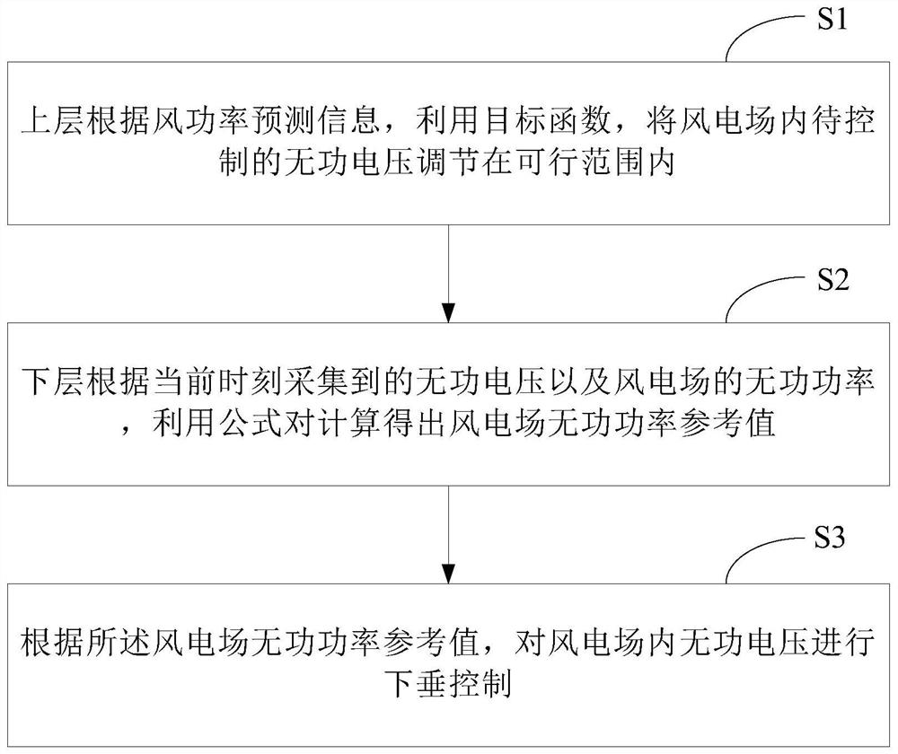
[0046] See figure 1 , figure 1 This is a schematic flowchart of a method for controlling reactive power and voltage in a wind farm provided by an embodiment of this application. by figure 1 It can be seen that the reactive voltage control method in the wind farm in this embodiment mainly includes the following processes:

[0047] S1: The upper layer uses the objective function according to the wind power prediction information Adjust the reactive voltage to be controlled in the wind farm within the feasible range.

[0048] Among them, the constraints are: Max and min are the maximum and minimum values ​​of the corresponding variables, and Upcc(k) is the reactive voltage value to be controlled at time k in the future, Is the target value of reactive voltage to be controlled, Q C Represents the reactive power provided by the capacitor; Q L Represents the reactive power consumed by the inductor.

[0049] In this embodiment, through the objective function, the reactive voltage to b...

Embodiment 2

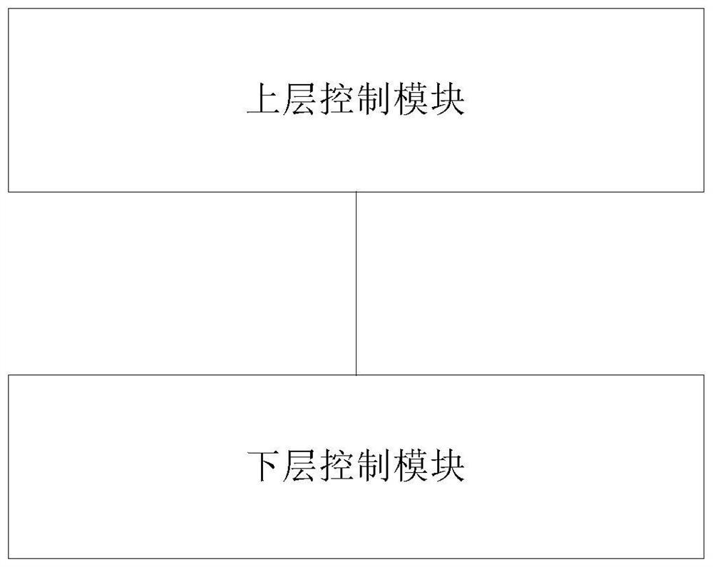
[0075] in figure 1 On the basis of the illustrated embodiment, see figure 2 , figure 2 This is a schematic structural diagram of a reactive voltage control system in a wind farm provided by an embodiment of this application. by figure 2 It can be seen that the structure of the reactive voltage control system in the wind farm in this embodiment mainly includes: an upper control module and a lower control module.

[0076] Among them, the upper control module is used to use the objective function according to the wind power prediction information Adjust the reactive voltage to be controlled in the wind farm within the feasible range, where the constraint conditions are: Max and min are the maximum and minimum values ​​of the corresponding variables, and Upcc(k) is the reactive voltage value to be controlled at time k in the future, Is the target value of reactive voltage to be controlled, Q C Represents the reactive power provided by the capacitor, Q L Represents the reactive p...


PUM


Abstract

The invention discloses a reactive voltage control method and system in a wind power plant. The method comprises the following steps that: according to wind power prediction information, an upper layer utilizes an objective function to adjust the reactive voltage to be controlled in the wind power plant to be within a feasible range, and according to the reactive voltage acquired at the current moment and the reactive power of the wind power plant, a lower layer utilizes a formula to calculate a reactive power reference value of the wind power plant, and droop control is carried out on the reactive voltage in the wind power plant according to the reactive power reference value of the wind power plant. The system comprises an upper-layer control module and a lower-layer control module. According to the invention, clean energy can be utilized to the greatest extent, and quick response of voltage control is realized, so that the reactive voltage control efficiency is improved.

Description

Technical field [0001] This application relates to the technical field of wind farm electrical control, and in particular to a method and system for controlling reactive power and voltage in a wind farm. Background technique [0002] Affected by the distribution of wind energy resources, a large number of large-scale wind farms are usually far away from the load center and connected to the end of the power grid. Such location settings make wind farms lack of effective voltage support from the system side. When the power of wind power fluctuates sharply in a short period of time, it is very easy to cause severe fluctuations in the voltage of the grid connection point, and it can even cause chain disconnection accidents and affect the safe and stable operation of the grid. As the mainstream model of the current wind farm, the doubly-fed wind turbine itself has a certain dynamic reactive power compensation capability. Therefore, how to make full use of the doubly-fed wind turbine to...

Claims


Application Information

Patent Timeline
Patent Type & Authority Applications(China)
IPC IPC(8): H02J3/16
CPCH02J3/16Y02E40/30
Inventor 李文博孙勇张世栋张林利刘合金刘洋王峰苏国强李帅张鹏平由新红黄敏
Owner ELECTRIC POWER RESEARCH INSTITUTE OF STATE GRID SHANDONG ELECTRIC POWER COMPANY
Learn More