Filling slurry mixing device for prefabricated building installation

A prefabricated assembly and mixing device technology, applied in mixers, transportation and packaging, mixer accessories, etc., can solve problems such as poor mixing quality, and achieve the effect of uniform blanking and accelerated mixing

Inactive Publication Date: 2020-09-11
胡勇强
View PDF0 Cites 2 Cited by
  • Summary
  • Abstract
  • Description
  • Claims
  • Application Information

AI Technical Summary

Problems solved by technology

[0004] Based on the technical problem of poor mixing quality of the filling slurry mixing device, t

Method used


Image

  • Filling slurry mixing device for prefabricated building installation
  • Filling slurry mixing device for prefabricated building installation
  • Filling slurry mixing device for prefabricated building installation

Examples


Embodiment 1

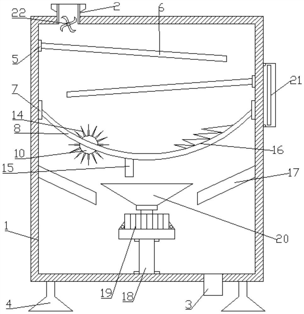
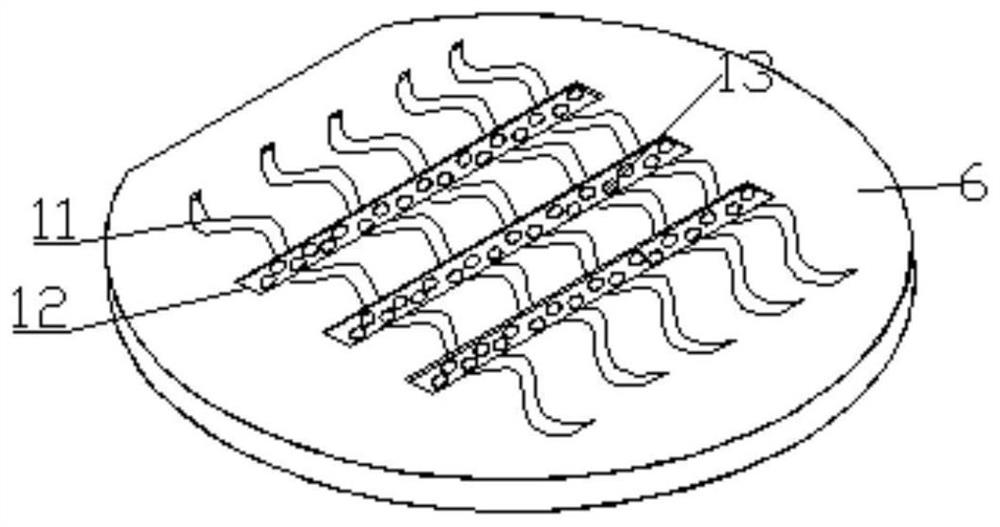
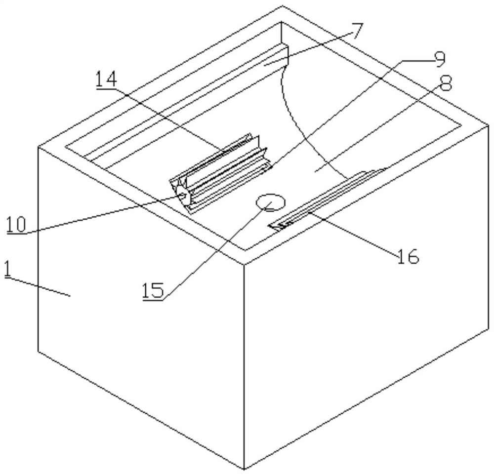
[0031] refer to Figure 1-4 , a prefabricated building installation filling slurry mixing device, comprising a box 1, the top side of the box 1 is provided with a feed pipe 2, the bottom side of the box 1 is provided with a second discharge pipe 3, the box 1 The inner walls on both sides are provided with two first fixed plates 5 distributed up and down. The inner sides of the two first fixed plates 5 are fixed with a mixing plate 6 . Evenly distributed first diversion grooves 11, the cross section of the first diversion grooves 11 is set in an S shape, two second fixing plates 7 are symmetrically fixed on the inner walls of the two sides of the box body 1, and two second fixing plates 7 are fixed between the two second fixing plates 7 For the same arc-shaped plate 8 , a first discharge pipe 15 is provided at the bottom of the arc-shaped plate 8 .

[0032] In the present invention, a plurality of longitudinally distributed second diversion grooves 12 are provided between the ...

Embodiment 2

[0036] refer to Figure 5, a prefabricated building installation filling slurry mixing device, the outer wall of the box body 1 away from the control panel 21 is fixed with an air storage tank 23, and the bottom of one of the upper mixing plates 6 is fixed with a main pipe 24, and the bottom of the main pipe 24 is set There are a plurality of evenly distributed sub-pipes 26, and the sub-pipes 26 are set to incline toward the other side of the mixing plate 6 located below, a connecting pipe 25 is connected between the main pipe 24 and the gas storage tank 23, and a heating wire is arranged inside the deflector 17 28. The inner sides of the tops of the two deflectors 17 are fixed with a flow limiting plate 29, and a groove 30 is formed inside the flow limiting plate 29. Structure notches.

[0037] When in use, start the gas storage tank 23, the gas inside enters the main pipe 24, blows out from the branch pipe 26, and blocks the flow of the slurry on the mixing plate 6, so that...


PUM


Abstract

The invention belongs to the technical field of buildings, particularly relates to a filling slurry mixing device for prefabricated building installation, and aims to solve the problem of poor mixingquality of the filling slurry mixing device. The device comprises a box body, a feeding pipe is arranged on one side of the top of the box body, a second discharging pipe is arranged on one side of the bottom of the box body, two first fixing plates distributed up and down are arranged on the inner walls of the two sides of the box body, and mixing plates are fixed to the inner sides of the two first fixing plates correspondingly and arranged obliquely downwards; a plurality of first flow guide grooves which are transversely and uniformly distributed are formed in the top of the mixing plates,the cross sections of the first flow guide grooves are S-shaped, two second fixing plates are symmetrically fixed to the inner walls of the two sides of the box body, an arc-shaped plate is fixed between the two second fixing plates, and a first discharging pipe is arranged at the bottom of the arc-shaped plate. According to the mixing device, the mixing plates are obliquely arranged in a staggered mode, and the multiple S-shaped first flow guide grooves are formed in the tops of the mixing plates, so that the turbulent flow effect on slurry is achieved, and the slurry is fully mixed.

Description

technical field [0001] The invention relates to the technical field of slurry mixing, in particular to a filling slurry mixing device for prefabricated building installation. Background technique [0002] Slurry is an organic substance with general colloidal properties. It can dissolve or swell in water and become a viscous and plastic paste. It can be used as a transfer agent for bringing dyes and other chemicals to fabrics. After printing and color fixing are completed, finally is washed away. In the process of building installation, filling slurry, etc. are needed, and the slurry generally needs to be mixed to achieve better results. [0003] In construction and installation, when mixing several types of slurry, it is usually done by manual mixing, which requires a lot of work, and it is not easy to achieve uniform mixing, and often the mixing effect will vary from person to person. Therefore, the stirring is not uniform enough and the product quality is not stable. At...

Claims


Application Information

Patent Timeline
IPC IPC(8): B01F13/10B01F13/02B01F15/06B01F33/40
CPCB01F33/4094B01F33/821B01F35/90B01F2101/28B01F2035/99
Inventor 胡勇强
Owner 胡勇强
Why Eureka
Try Eureka