
Drilling device for valve processing

A drilling device and valve technology, used in metal processing, boring/drilling, metal processing equipment, etc., can solve the problems of complex structure and inconvenient operation, and achieve the goal of optimizing the structure, reducing the driving device and improving the drilling efficiency. Effect

Inactive Publication Date: 2020-09-11
何立
View PDF0 Cites 1 Cited by
  • Summary
  • Abstract
  • Description
  • Claims
  • Application Information

AI Technical Summary

Problems solved by technology

[0003] Drilling is required in the process of valve processing, and the existing drilling device drives the drill rod to rotate through a driving device when drilling, and then sets another driving device to realize the feeding of the drill rod, which is not only complicated in structure, but also Need to be controlled separately, inconvenient to operate

Method used


Image

  • Drilling device for valve processing
  • Drilling device for valve processing
  • Drilling device for valve processing

Examples


Embodiment 1

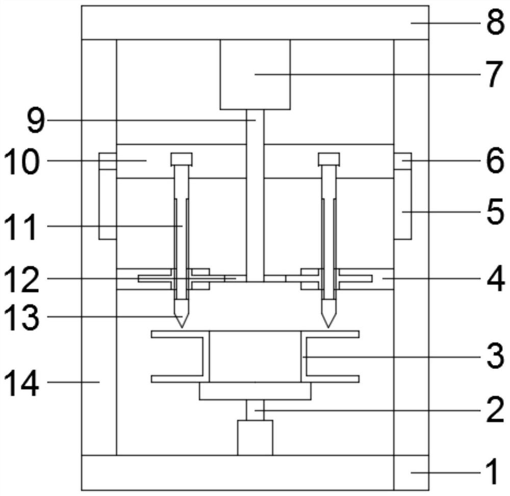
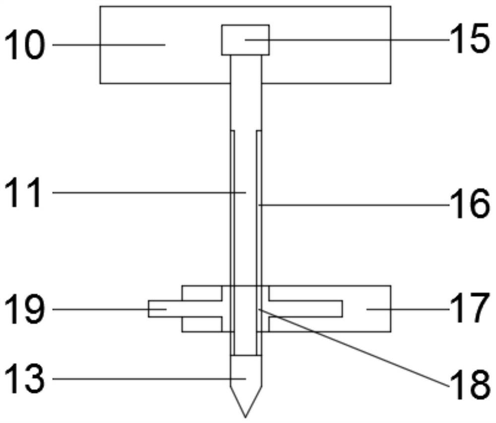
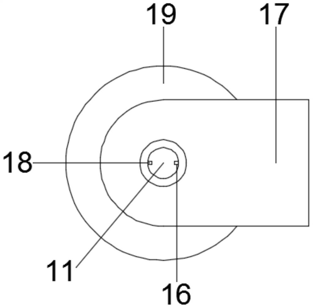
[0023] Such as figure 1 , 2 . The drilling device for valve processing shown in 3 includes a base 1, the upper surface of the base 1 is fixedly installed with a support platform 2 for supporting the valve 3, that is, the drilling work is performed by supporting the valve 3 on the support platform 2; Both sides of the support platform 2 are equipped with fixed plates 14 fixedly connected to the base 1, and the upper ends of the two fixed plates 14 are fixedly connected through the top plate 8, and the bottom of the top plate 8 is fixedly equipped with the first rotating motor 7. The output end of the bottom of the first rotating motor 7 is fixedly equipped with a first threaded rod 9, and the outer side of the bottom of the first threaded rod 9 is fixedly mounted with a gear plate 12, and the outside of the first threaded rod 9 is provided with a slide plate threaded therewith 10. The two ends of the slide plate 10 are respectively slidingly connected to the two fixed plates 1...

Embodiment 2

[0028] This embodiment is further optimized on the basis of embodiment 1, as Figure 4 , 5 As shown, in order to facilitate multiple drilling, the support table 2 includes a second rotating motor 20 and a supporting plate 21, the second rotating motor 20 is fixedly installed on the upper surface of the base 1, and the supporting plate 21 is arranged on the second The top of the second rotating motor 20 is fixedly connected to its output end, that is, the valve 3 on the support plate 21 is rotated by the second rotating motor 20, so as to perform multiple drilling operations at different positions; in order to ensure that the valve 3 is drilled In order to ensure the stability of the hole, the upper end of the support plate 21 is equipped with a fixing mechanism 22 for fixing the valve 3 .

[0029] Further, the fixing mechanism 22 includes a second threaded rod 23 fixedly installed on the upper surface of the support plate 21, and the outside of the second threaded rod 23 is s...


PUM


Abstract

The invention relates to a drilling device for valve processing and belongs to the technical field of valve processing equipment. The drilling device comprises a base, wherein two fixing plates and asupporting table are mounted on the upper surface of the base; the supporting table is used for supporting a valve; a first rotating motor is fixedly mounted at the bottom of a top plate positioned atthe tops of the fixing plates; a first threaded rod is mounted at the bottom of the first rotating motor; a gear plate is mounted at the bottom of the first threaded rod; the first threaded rod is sleeved by a sliding plate which is in threaded connection with the first threaded rod; two ends of the sliding plate are slidably connected with the fixing plates; and drilling rods which are rotationally connected with the sliding plate are mounted at the bottom of the sliding plate and connected with the gear plate through transmission mechanisms. The rotating drilling operation can be achieved when the drilling rods are adjusted to rise and fall; not only can the arrangement of driving equipment be reduced and the structure be optimized, but also the control can be more convenient and stable, the drilling efficiency can be improved, and more energy can be saved; and through the arrangement of a rotatable supporting plate equipped with a fixing mechanism, the valve can be conveniently fixed and rotationally adjusted, the repeated drilling operation can be facilitated, and the practicability can be improved.

Description

technical field [0001] The invention relates to the technical field of valve processing equipment, in particular to a drilling device for valve processing. Background technique [0002] The valve is a pipeline accessory used to open and close the pipeline, control the flow direction, adjust and control the parameters (temperature, pressure and flow) of the conveying medium. It is mainly used to control the flow of various types of fluids such as air, water, steam, various corrosive media, mud, oil, liquid metal and radioactive media. [0003] Drilling is required in the process of valve processing, and the existing drilling device drives the drill rod to rotate through a driving device when drilling, and then sets another driving device to realize the feeding of the drill rod, which is not only complicated in structure, but also It needs to be controlled separately, which is inconvenient to operate. Contents of the invention [0004] The purpose of the present invention ...

Claims


Application Information

Patent Timeline
Patent Type & Authority Applications(China)
IPC IPC(8): B23B41/00B23Q7/00
CPCB23B41/00B23Q7/00
Inventor 何立
Owner 何立
Learn More