An assembled bottle cap injection molding process

An assembled and bottle cap technology, which is applied to threaded products, household appliances, household components, etc., can solve the problem of inconvenient demoulding of bottle caps, and achieve the effects of easy demoulding, convenient production, and convenient twisting and separation

Active Publication Date: 2022-04-08
青岛泷友制盖有限公司
View PDF7 Cites 0 Cited by
  • Summary
  • Abstract
  • Description
  • Claims
  • Application Information

AI Technical Summary

Problems solved by technology

[0004] For this reason, the embodiment of the present invention provides an assembled bottle cap injection molding process. The bottle cap convex mold and the bottle cap concave mold are used for injection molding, and the push rod is rotated to push the fixed rod to realize the rotation of the turret. The cap rotates, and the spiral pattern formed inside the bottle cap is separated from the fixed spiral groove on the outer surface of the convex mold of the bottle cap, which facilitates the demoulding of the bottle cap and prevents the spiral pattern inside the bottle cap from affecting the opening and closing operation of the injection mold. In the prior art, due to the tight combination of the spiral pattern inside the bottle cap and the mold during the injection molding process, the problem caused by the inconvenient demoulding of the bottle cap

Method used


Image

  • An assembled bottle cap injection molding process
  • An assembled bottle cap injection molding process
  • An assembled bottle cap injection molding process

Examples


Embodiment 1

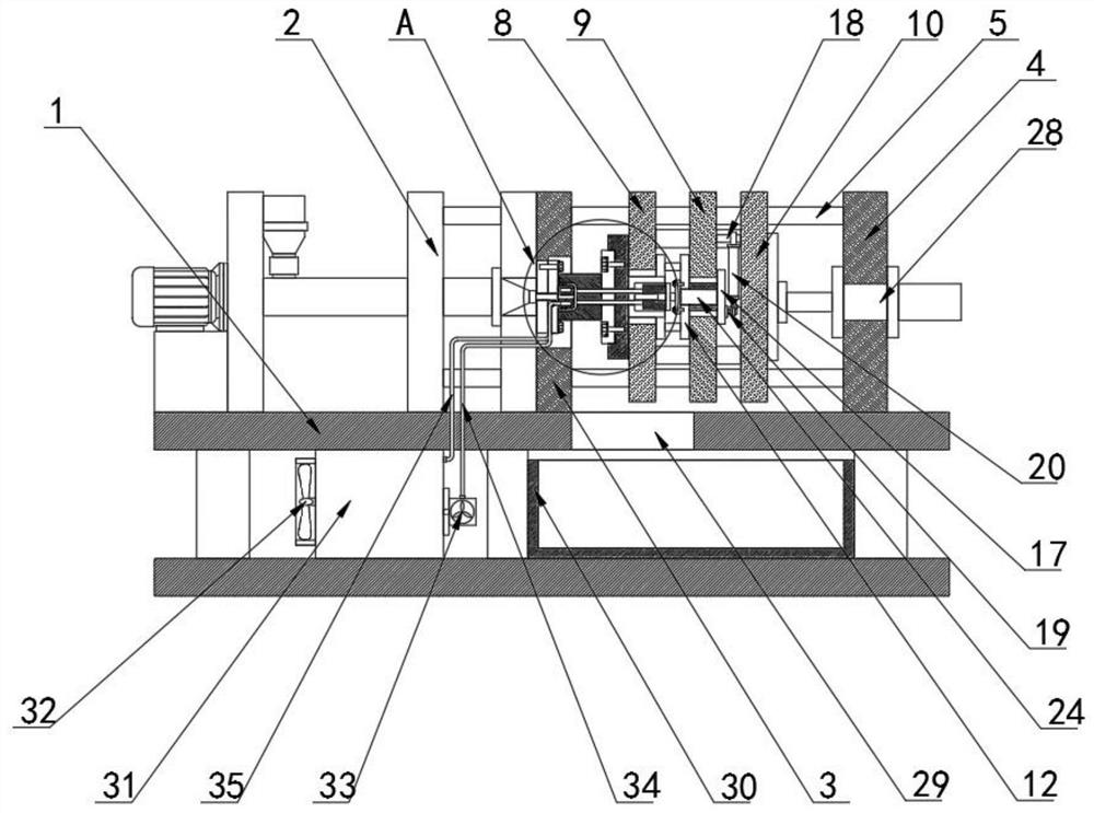
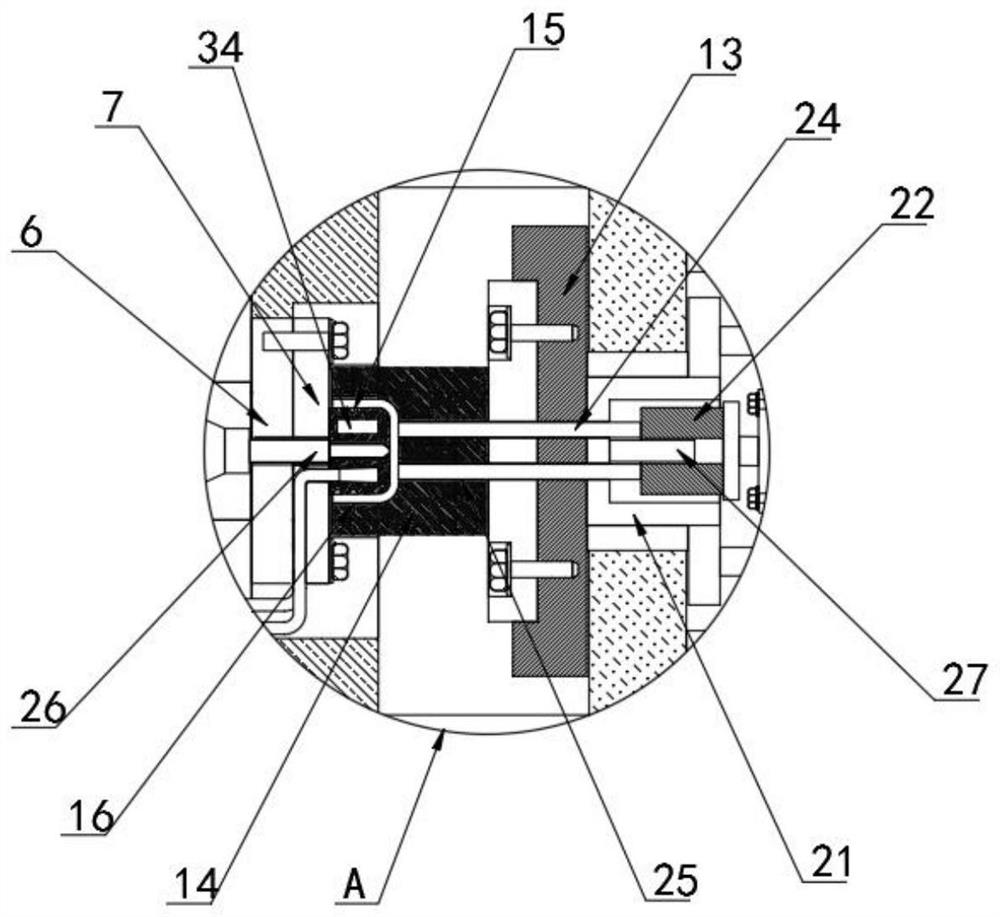
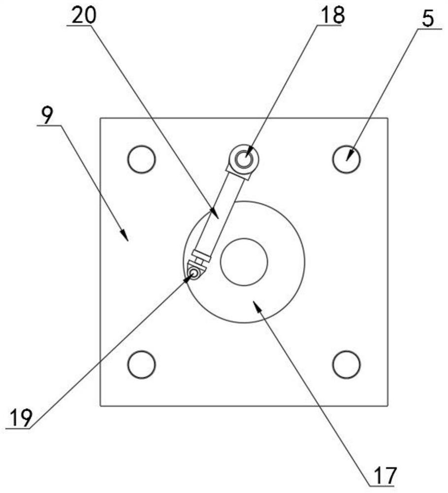
[0037] Refer to the attached Figure 1-7, an assembled bottle cap injection molding process in this embodiment, comprising a mold body 1, an injection molding frame 2 is fixedly arranged at one end of the top of the mold body 1, and a first fixed mold plate is fixedly arranged on one side of the injection molding frame 2 3. The other end of the top of the mold body 1 is fixedly provided with a second fixed mold plate 4, between the four corners of the first fixed mold plate 3 and the second fixed mold plate 4 there are fixed guide bars 5, the first The middle part of the fixed mold plate 3 is fixedly provided with a fixed mounting plate 6, the middle surface of the fixed mounting plate 6 is detachably provided with a bottle cap convex mold 7, and the surface of the guide slide bar 5 is sequentially provided with a first movable plate from left to right 8. The second movable plate 9 and the third movable plate 10, connecting columns 11 are fixed between the first movable plate ...

Embodiment 2

[0046] An injection molding process of an assembled bottle cap injection molding process, the specific operation steps are as follows:

[0047] Step 1: Select the corresponding bottle cap convex mold 7 and bottle cap concave mold 14, install the bottle cap convex mold 7 on the fixed mounting plate 6, and install the bottle cap concave mold 14 on the rotating mounting plate 13;

[0048] Step 2: Operate the mold opening and closing hydraulic cylinder 28 to push the third movable plate 10, drive the bottle cap convex mold 7 and the bottle cap concave mold 14 to perform mold clamping operation, and the subsequent injection molding equipment delivers the molten injection plastic to the bottle through the injection molding inlet pipe 26 In the injection molding space formed by the cap convex mold 7 and the bottle cap concave mold 14;

[0049] Step 3: The delivery pump 33 extracts the cooling water in the cooling water tank 31, and uses the water inlet pipe to transport it to the coo...


PUM


Abstract

The invention discloses an assembled bottle cap injection molding process, which specifically relates to the technical field of injection molds. Injection injection pipe transports molten injection plastic to the injection space formed by the bottle cap convex mold and the bottle cap concave mold; Step 3: Realize water circulation, and at the same time, the cooling fan performs air cooling for the cooling water tank; Step 4: Realize the bottle cap and the mold Step 5: The bottle caps that have escaped from the mold fall through the window into the receiving box for collection. In the present invention, the bottle cap convex mold and the bottle cap concave mold are used for injection molding, and the push rod is rotated to push the fixed rod to realize the rotation of the turret, and the formed bottle cap is rotated. The outer side of the mold surface is fixed with a spiral groove separation, which facilitates the demoulding of the bottle cap and prevents the spiral pattern inside the bottle cap from affecting the opening and closing operation of the injection mold.

Description

technical field [0001] The invention relates to the technical field of injection molds, in particular to an injection molding process for assembled bottle caps. Background technique [0002] The bottle cap is used to seal the bottle. According to different functions, there are bottle caps with different shapes and different operation methods. The advantages of the injection molding method are fast production speed, high efficiency, automatic operation, various designs and colors, simple to complex shapes, large to small sizes, accurate product sizes, easy replacement of products, and complex shapes. Parts, injection molding is suitable for mass production and complex shape products and other molding processing fields. At a certain temperature, the completely molten plastic material is stirred by a screw, injected into the mold cavity with high pressure, and cooled and solidified to obtain a molded product. This method is suitable for mass production of parts with complex s...

Claims


Application Information

Patent Timeline
Patent Type & Authority Patents(China)
IPC IPC(8): B29C45/26B29C45/40B29C45/67B29C45/73B29L31/56B29L1/00
CPCB29C45/2618B29C45/262B29C45/401B29C45/67B29C45/7312B29C45/7337B29L2031/56B29L2001/00
Inventor 梁慧郭旭伦
Owner 青岛泷友制盖有限公司
Why Eureka
Try Eureka