A driving force recovery control method, device and 48v drive system
A recovery control and driving force technology, applied in the direction of climate sustainability, road transportation, sustainable transportation, etc., can solve problems affecting taxiing distance, etc., and achieve the effect of reducing time
- Summary
- Abstract
- Description
- Claims
- Application Information
AI Technical Summary
Problems solved by technology
Method used
Image

Examples
Embodiment 1
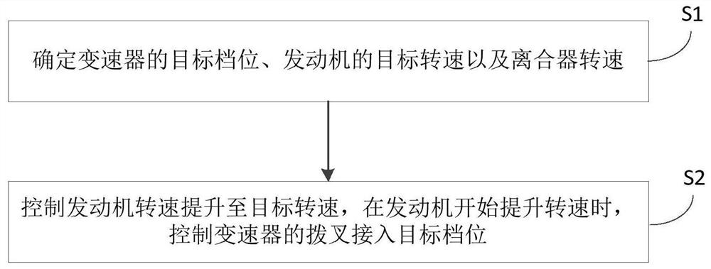
[0031] figure 1 It is the flow chart of the control method in Embodiment 1. This embodiment is applicable to the situation where the driving force of the vehicle is restored when the vehicle is switched from the coasting mode to the driving mode when the vehicle is stopped. way, the device can be configured in electronic equipment, such as in the transmission control unit TCU, such as figure 1 As shown, the method may specifically include:
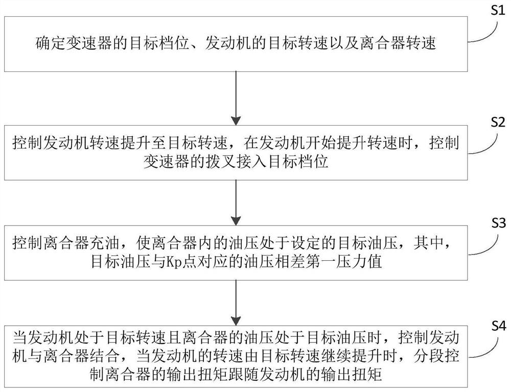
[0032] S1. Determine the target gear of the transmission, the target speed of the engine and the speed of the clutch.
[0033] Exemplarily, in this embodiment, the transmission device adopts a wet dual-clutch transmission, and the wet dual-clutch transmission generally includes a shift fork, two sets of gears, one input shaft, two output shafts, two clutches, two solenoid valves and A hydraulic pump, in which two sets of gears are respectively arranged on one output shaft, for example, one output shaft is equipped with 1st gear, 3rd gear...
Embodiment 2
[0070] This embodiment proposes a driving force recovery control device, the control device is configured in the transmission control unit, the control device includes a driving force recovery module, and the driving force recovery module is used for:
[0071] When the driving condition is switched from the stop coasting mode to the driving mode, determine the target gear position of the transmission, the target engine speed and the clutch speed; control the engine speed to increase to the target speed, and control the shift fork connection of the transmission when the engine starts to increase the speed into the target gear, wherein the target gear matches the clutch speed.
[0072] Optionally, when the transmission control unit controls the shift fork of the transmission to enter the target gear:
[0073] The driving force recovery module is used to control the oil filling of the clutch so that the oil pressure in the clutch is at a set target oil pressure, wherein the targe...
Embodiment 3
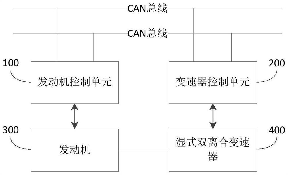
[0079] refer to figure 2 , this embodiment proposes a 48V drive system, including an engine control unit 100 and a transmission control unit 200 .
[0080] The engine control unit 100 is connected to the engine 300 , the transmission control unit 200 is connected to the wet dual-clutch transmission 400 , and the engine control unit 100 is communicatively connected to the transmission control unit 200 through the CAN bus.
[0081] In this embodiment, the transmission control unit 200 is used to implement the driving force recovery control method described in the first embodiment, and the beneficial effect is the same as that described in the first embodiment.
PUM
 Abstract
Description
Claims
Application Information
 - R&D
- Intellectual Property
- Life Sciences
- Materials
- Tech Scout
- Unparalleled Data Quality
- Higher Quality Content
- 60% Fewer Hallucinations
Browse by: Latest US Patents, China's latest patents, Technical Efficacy Thesaurus, Application Domain, Technology Topic, Popular Technical Reports.
© 2025 PatSnap. All rights reserved.Legal|Privacy policy|Modern Slavery Act Transparency Statement|Sitemap|About US| Contact US: help@patsnap.com