
Quick lifting mechanism applied to bridge construction

A technology of bridges and mobile frames, which is applied in bridge construction, bridges, traveling mechanisms, etc. It can solve the problems of rapid falling, tilting and shaking of lifted components and materials, hidden dangers of construction safety, etc., and achieve the effect of improving stability and convenience, and improving Stability and efficiency, and the effect of reducing construction safety hazards

Inactive Publication Date: 2020-09-11
吕友飞
View PDF7 Cites 4 Cited by
  • Summary
  • Abstract
  • Description
  • Claims
  • Application Information

AI Technical Summary

Problems solved by technology

[0007] The purpose of the present invention is to provide a kind of rapid lifting mechanism that is applied to bridge construction, to solve the above-mentioned background technology, it is inconvenient to artificially adjust the installation and use position of the existing rapid lifting mechanism that is applied to bridge construction when it is in use. Adjustment changes and limit positions make the mechanism prone to overall tilting and shaking due to unilateral force during use, resulting in overall shaking and falling of the materials and accessories it lifts. At the same time, there are serious construction safety hazards. At the same time, when the mechanism During the lifting operation, the limit protection measures are not good, and it is easy to cause local damage to the components during the lifting work, resulting in the rapid fall of the lifted components and materials under the action of gravity, causing the personal safety of the construction personnel to be threatened by the construction , the problem of not being able to effectively buffer and limit the speed of gravity falling

Method used


Image

  • Quick lifting mechanism applied to bridge construction
  • Quick lifting mechanism applied to bridge construction
  • Quick lifting mechanism applied to bridge construction

Examples


Embodiment Construction

[0029] The following will clearly and completely describe the technical solutions in the embodiments of the present invention with reference to the accompanying drawings in the embodiments of the present invention. Obviously, the described embodiments are only some, not all, embodiments of the present invention. Based on the embodiments of the present invention, all other embodiments obtained by persons of ordinary skill in the art without making creative efforts belong to the protection scope of the present invention.

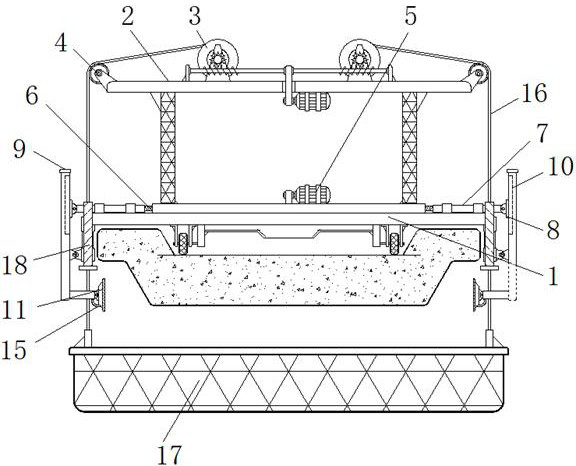
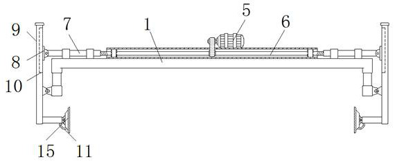
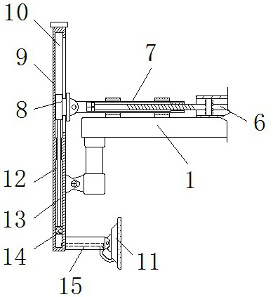
[0030] see Figure 1-8 , the present invention provides a technical solution: a rapid lifting mechanism applied to bridge construction, including a mobile frame 1, a truss 2, a winding wheel 3, a guide wheel 4, a motor track assembly 5, a screw rod 6, and a support tube 7 , sliding support 8, support frame 9, chute 10, air seal suction cup 11, air cavity 12, push rod 13, air seal rubber block 14, threaded hose 15, steel rope 16, hanging basket 17, positioning ...


PUM


Abstract

The invention discloses a quick lifting mechanism applied to bridge construction. The quick lifting mechanism comprises a movable rack, a motor crawler belt assembly and a hanging basket. The A trussis fixedly mounted on the top of the movable rack. The motor crawler belt assembly is fixedly mounted on the outer wall of the top of the movable rack. The outer wall of the end of the movable rack ishinged to the outer wall of the middle portion of a supporting frame. The upper half portion of the supporting frame is internally provided with sliding grooves. Wire ropes are wound on the outer walls of winding wheels and are attached to the outer walls of guide wheels. The hanging basket is fixed to the lower ends of the wire ropes. The edges of the ends of the movable rack are fixedly connected with locating tubes. The quick lifting mechanism applied to bridge construction facilitates position movement and change and positioning operation. The positioning and installation stability and efficiency of the mechanism are improved. Meanwhile, the quick lifting mechanism can be protected against falling in the using process. Potential construction safety hazards of the quick lifting mechanism during lifting motion are effectively reduced.

Description

technical field [0001] The invention relates to the technical field related to bridge construction, in particular to a rapid lifting mechanism applied to bridge construction. Background technique [0002] The existing bridge construction, according to the different construction techniques, is mainly divided into two types: form pouring construction and prefabricated assembly construction. In different types of construction, it is necessary to install a lifting mechanism to complete the construction of the bridge. Operation, to avoid the omission of bottom reinforcement and the inconvenience of construction operation during the construction of the bridge. At the same time, the use of the lifting mechanism can facilitate the construction and reinforcement of the bridge bottom structure, as well as the installation and positioning of bridge construction accessories. [0003] However, the existing rapid lifting mechanism applied to bridge construction has the following problems ...

Claims


Application Information

Patent Timeline
IPC IPC(8): B66C5/02B66C13/06B66C15/00B66C9/18B66D5/16E01D21/00
CPCB66C5/02B66C9/18B66C13/06B66C15/00B66D5/16E01D21/00
Inventor 吕友飞
Owner 吕友飞
Learn More