
Air-conditioning system achieving continuous heating

An air-conditioning system and a technology connected to it, which is applied in the direction of air-conditioning systems, refrigerators, heating methods, etc., can solve the problems of low temperature of the refrigerant in the outdoor heat exchanger, lower indoor temperature, and poor user experience, so as to achieve simple control and convenient use , design reasonable effect

Inactive Publication Date: 2020-09-11
NANJING TICA AIR CONDITIONING CO LTD
View PDF6 Cites 0 Cited by
  • Summary
  • Abstract
  • Description
  • Claims
  • Application Information

AI Technical Summary

Problems solved by technology

[0002] When the heat pump air conditioner is running for heating, the outdoor heat exchanger absorbs heat from the environment. As the outdoor ambient temperature drops, the temperature of the refrigerant in the outdoor heat exchanger will be lower than 0°C. At this time, frosting will occur, and the frosting will gradually increase. Thickness reduces the outdoor circulating air volume, lowers the temperature of the refrigerant in the outdoor heat exchanger, and affects the heating effect
[0003] In a conventional air conditioning system, the amount of frosting is judged by detecting the temperature of the outdoor heat exchanger. When the amount of frosting reaches the threshold, the four-way valve is switched to allow high-temperature and high-pressure refrigerant to enter the outdoor heat The low-pressure refrigerant enters the indoor heat exchanger to evaporate and absorb heat, and the indoor environment cannot continue to supply heat but also absorbs heat, resulting in a significant drop in indoor temperature and poor user experience

Method used


Image

  • Air-conditioning system achieving continuous heating
  • Air-conditioning system achieving continuous heating
  • Air-conditioning system achieving continuous heating

Examples


Embodiment Construction

[0019] The present invention will be further described below in conjunction with the accompanying drawings and embodiments.

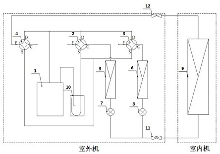
[0020] Such as figure 1 shown.

[0021] An air-conditioning system for continuous heating, including an outdoor unit and an indoor unit connected through a liquid pipe and a gas pipe. The liquid pipe and the gas pipe are respectively provided with a liquid pipe shut-off valve 11 and a gas pipe shut-off valve 12, which can control the on-off of the liquid pipe and the gas pipe.

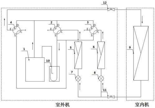
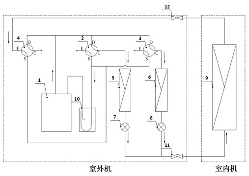
[0022] The outdoor unit includes a compressor 1 , a four-way valve I2 , a four-way valve II3 , a four-way valve III4 , an outdoor heat exchanger I5 , an outdoor heat exchanger II6 and a gas-liquid separator 10 . The indoor unit includes an indoor heat exchanger 9 . Preferably, the compressor 1 is a rotary compressor or a scroll compressor. Both the expansion valve I7 and the expansion valve II8 are electronic expansion valves.

[0023] The D end of the four-way valve I2, th...


PUM


Abstract

The invention relates to an air-conditioning system achieving continuous heating. The D end of a four-way valve I, the D end of a four-way valve II and the D end of a four-way valve III are mutually connected in parallel and then connected to an exhaust port of a compressor; the E end of the four-way valve III is connected with the air end of an indoor heat exchanger, the C end of the four-way valve I is connected with the air end of an outdoor heat exchanger I, and the C end of the four-way valve II is connected with the air end of an outdoor heat exchanger II; the S end of the four-way valveI, the S end of the four-way valve II and the S end of the four-way valve III are mutually connected in parallel and then connected to an inlet of an air-liquid separator; an outlet of the air-liquidseparator is connected with a suction port of the compressor; the liquid end of the outdoor heat exchanger I and the liquid end of the outdoor heat exchanger II pass through an expansion valve I andan expansion valve II respectively to be mutually connected in parallel and then connected to the liquid end of the indoor heat exchanger; and the E end of the four-way valve I, the E end of the four-way valve II and the C end of the four-way valve III are all closed. It is guaranteed that the air-conditioning system achieving continuous heating can continuously supply heat to the indoor.

Description

technical field [0001] The invention relates to an air-conditioning system, in particular to an air-conditioning system capable of continuous heating, in particular to an air-conditioning system capable of continuous heating. Background technique [0002] When the heat pump air conditioner is running for heating, the outdoor heat exchanger absorbs heat from the environment. As the outdoor ambient temperature drops, the temperature of the refrigerant in the outdoor heat exchanger will be lower than 0°C. At this time, frosting will occur, and the frosting will gradually increase. Thickness reduces the outdoor circulating air volume, lowers the temperature of the refrigerant in the outdoor heat exchanger, and affects the heating effect. [0003] In a conventional air conditioning system, the amount of frosting is judged by detecting the temperature of the outdoor heat exchanger. When the amount of frosting reaches the threshold, the four-way valve is switched to allow high-temp...

Claims


Application Information

Patent Timeline
Patent Type & Authority Applications(China)
IPC IPC(8): F25B13/00F25B41/04F25B41/06F25B43/00F25B47/02F25B49/02F24F1/0003F24F5/00F24F11/41F24F11/64F24F11/65F24F11/84
CPCF24F1/0003F24F5/001F25B13/00F25B43/006F25B47/02F25B49/02F24F11/41F24F11/64F24F11/65F24F11/84
Inventor 谭秋晖杨亚华徐来福
Owner NANJING TICA AIR CONDITIONING CO LTD
Learn More