Heat conduction rake of vacuum rake dryer

A rake dryer and dryer technology, which is used in dryers, drying solid materials, and dry goods processing, etc., can solve the problem that the inner pipe wall is easy to stick to thick dirt, the distance between the end of the rake and the inner cylinder wall is large, and the Problems such as small heat transfer area, to achieve the effect of improving the quality of dried products, improving drying quality and uniform heat transfer

Inactive Publication Date: 2020-09-11
JIANGSU BOSIWEI ENG TECH CO LTD
View PDF13 Cites 3 Cited by
  • Summary
  • Abstract
  • Description
  • Claims
  • Application Information

AI Technical Summary

Problems solved by technology

[0002] The heat transfer area of ​​the existing vacuum rake drying rake rod is small; the distance between the end of the rake and the inner tube wa

Method used


Image

  • Heat conduction rake of vacuum rake dryer
  • Heat conduction rake of vacuum rake dryer
  • Heat conduction rake of vacuum rake dryer

Examples


Embodiment Construction

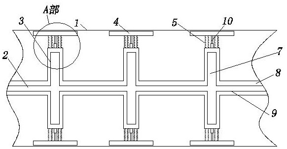
[0026] A heat-conducting rake of a vacuum rake dryer, the dryer 1 is provided with a rake shaft 2, and the rake shaft 2 is axially distributed with several radially arranged rake discs 3, the rake shaft 2, rake disc 3 are connected and all are hollowly arranged to form a cavity, and heat medium is passed into the cavity;

[0027] Both the rake shaft 2 and the rake disc 3 are separated into an inner layer 7 and an outer layer 8 by a partition 9, the outer layer 8 is provided with a liquid medium, and the inner layer 7 is provided with a gas medium.

[0028] Further, the liquid medium is contained in the outer layer 8 in a static manner, and the gas medium is arranged in the inner layer 7 in a flowing manner.

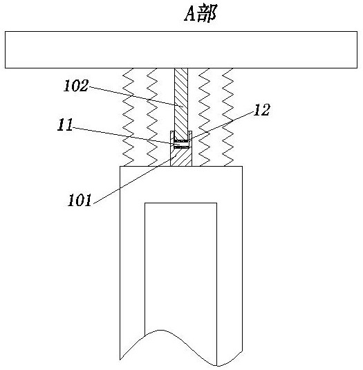
[0029] Further, a number of scrapers 4 are arranged on the outer peripheral edge of the rake plate 3, and the scrapers 4 are made of elastic materials. Set arc shape.

[0030] Further, the scrapers 4 are uniformly arranged on the rake disc 3 in the circumferential direc...


PUM


Abstract

The present invention relates to a heat conduction rake of vacuum rake dryer. A rake shaft is arranged in the dryer, a plurality of radially arranged rake plates are distributed in the rake shaft in the axial direction, the rake shaft and the rake plates communicate with each other and are hollow to form a cavity, and a thermal medium is introduced into the cavity; and the rake shaft and the rakeplates are divided into inner layers and outer layers by partition plates, a liquid medium is arranged in the outer layers in a communication manner, and a gas medium is arranged in the inner layer ina communication manner. According to the heat conduction rake, a traditional rake rod is changed into the structural form of the rake plates, the heat transfer area is increased, the heat efficiencyis improved, the generation of dirt on an inner cylinder wall is avoided, the quality of the dried product is improved, the mixing is uniform, and the overall drying quality is improved; and meanwhile, a plurality of scraping plates are arranged on the edges of the outer sides of the rake plates, materials can be further disturbed by the scraping plates, the materials on the inner wall of the dryer are scraped by the scraping plates at the same time, the scraping plates are elastically arranged, abrasion of the scraping plates and the inner wall of the dryer is reduced, and the service life ofthe scraping plates is prolonged.

Description

technical field [0001] The invention relates to a heat conduction rake of a vacuum rake dryer, which belongs to the technical field of dryers. Background technique [0002] The heat transfer area of ​​the existing vacuum rake drying rake rod is small; the distance between the end of the rake and the inner tube wall is relatively large, and thick dirt is easy to accumulate on the inner tube wall, which affects the thermal efficiency, so it needs to be improved. Contents of the invention [0003] The purpose of the present invention is to provide a heat conduction rake for a vacuum rake dryer with a reasonable structure and improved heat transfer area. [0004] For this reason, the technical solution adopted by the present invention is: a heat-conducting rake of a vacuum rake dryer, the dryer (1) is provided with a rake shaft (2), and a number of The rake disc (3) arranged radially, the rake shaft (2) and the rake disc (3) are connected and both are hollowly arranged to for...

Claims


Application Information

Patent Timeline
IPC IPC(8): F26B25/00F26B25/04F26B5/04F26B21/00
CPCF26B5/04F26B21/004F26B25/001F26B25/04
Inventor 任红兵党梅任智博吴小艳
Owner JIANGSU BOSIWEI ENG TECH CO LTD
Why Eureka
Try Eureka