Improved structure of electrical cabinet
A technology for electrical cabinets and cabinets, applied in the field of electric control cabinets, can solve problems such as uneven heat dissipation and affecting the use of electronic components, and achieve the effect of improving uniformity
- Summary
- Abstract
- Description
- Claims
- Application Information
AI Technical Summary
Problems solved by technology
Method used
Image

Examples
Embodiment 1
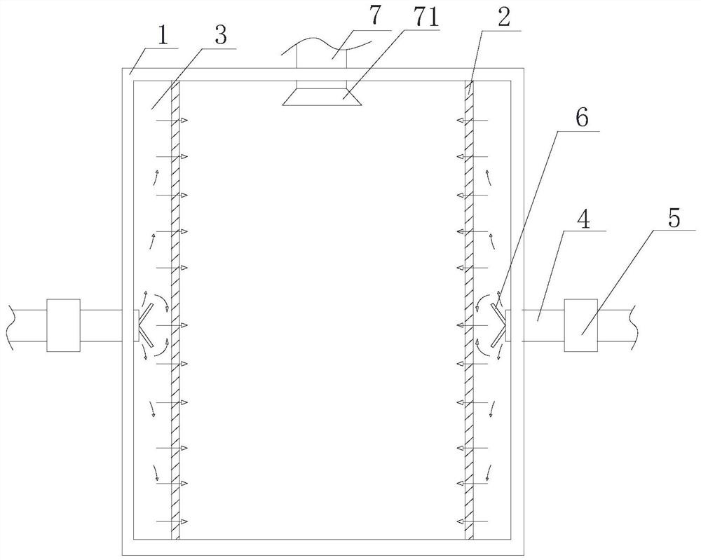
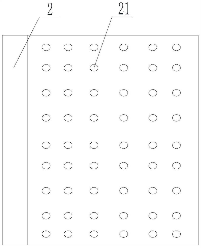
[0043] Such as Figure 1-Figure 2 , Figure 4 As shown, an improved structure of an electrical cabinet includes a cabinet body 1 and a cover plate that cooperate with each other, and two L-shaped baffles 2 are symmetrically arranged inside the cabinet body 1, and the two sides of the L-shaped baffles 2 The ends are respectively connected to two adjacent side walls of the cabinet 1, and the two L-shaped ends of the L-shaped baffle 2 are respectively in contact with the top wall and the bottom wall of the cabinet 1, and the L-shaped baffle 2 A buffer cavity 3 is formed between the cabinet body 1, and the airflow entering through the air inlet pipe 4 is buffered in the buffer cavity 3. A number of ventilation holes 21 are provided on the side of the L-shaped baffle 2 perpendicular to the air intake direction. , the ventilation holes 21 are only arranged on the side perpendicular to the air inlet direction, which can avoid the reduction of the buffering effect caused by the venti...
Embodiment 2
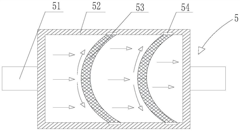
[0047] Such as Figure 1-Figure 3 As shown, this embodiment is based on Embodiment 1, and the drying device 5 includes a housing 52, two ends of the housing 52 are provided with installation pipes 51, and a drying plate 53 is arranged inside the housing 52, and the drying plate 53 is an arc-shaped plate protruding toward the air inlet; two drying plates 53 are arranged in parallel in the housing 52; the drying plate 53 is a mesh-like drying structure, including a filter screen and a desiccant.
[0048] In this embodiment, by making the drying plate 53 an arc-shaped plate protruding toward the air inlet end, the airflow entering the housing 52 can be guided to diffuse, improve the uniformity of the airflow contacting the drying plate 53 and reduce the airflow in the air. Velocity in housing 52.
Embodiment 3
[0050] Such as Figure 1-Figure 3As shown, this embodiment is based on Embodiment 2, and both ends of the drying plate 53 are provided with protrusions 54, and the inner wall of the housing 52 is provided with a slot that cooperates with the protrusion 54, and the protrusion 54 is inserted into the slot The detachable connection between the drying plate 53 and the housing 52 is realized. The housing 52 includes a matching installation frame and a cover plate, and the cover plate is detachably connected with the installation frame.
PUM
| Property | Measurement | Unit |
|---|---|---|
| Angle | aaaaa | aaaaa |
Abstract
Description
Claims
Application Information
 - R&D
- Intellectual Property
- Life Sciences
- Materials
- Tech Scout
- Unparalleled Data Quality
- Higher Quality Content
- 60% Fewer Hallucinations
Browse by: Latest US Patents, China's latest patents, Technical Efficacy Thesaurus, Application Domain, Technology Topic, Popular Technical Reports.
© 2025 PatSnap. All rights reserved.Legal|Privacy policy|Modern Slavery Act Transparency Statement|Sitemap|About US| Contact US: help@patsnap.com