
Auxiliary stent for puncture

An auxiliary stent and threaded rod technology, applied in medical science, hospital beds, hospital equipment, etc., can solve the problems of excessive limb movement, affecting the prognosis of the puncture site, unfavorable puncture points for patients and recovery of the surgical limb, etc., to improve comfort, avoid Stiff or uncomfortable effects

Inactive Publication Date: 2020-09-15
孙利平
View PDF0 Cites 6 Cited by
  • Summary
  • Abstract
  • Description
  • Claims
  • Application Information

AI Technical Summary

Problems solved by technology

[0004] Aiming at the deficiencies of the prior art, the present invention provides an auxiliary stent for puncture, which solves the problem that the wristband-type hemostatic airbag proposed in the above-mentioned background technology is worn on the patient’s wrist in the form of a wristwatch and plays a hemostatic effect, but some Patient compliance is poor, the wrist cannot be immobilized, and excessive movement of the limbs is prone to occur, that is, excessive movement of the wrist will affect the prognosis of the puncture site, especially during meals and sleep, often due to unconscious turning movements. Or the body is pressed against the operative limb and the puncture site, resulting in bleeding at the puncture site, hematoma, and peripheral blood supply disorders, which is not conducive to the recovery of the patient's puncture point and the operative limb, and may even cause serious complications.

Method used


Image

  • Auxiliary stent for puncture
  • Auxiliary stent for puncture
  • Auxiliary stent for puncture

Examples


Embodiment Construction

[0028] The following will clearly and completely describe the technical solutions in the embodiments of the present invention with reference to the accompanying drawings in the embodiments of the present invention. Obviously, the described embodiments are only some, not all, embodiments of the present invention.

[0029] In the description of the present invention, unless otherwise stated, the meaning of "plurality" is two or more; the terms "upper", "lower", "left", "right", "inner", "outer" , "front end", "rear end", "head", "tail", etc. indicate the orientation or positional relationship based on the orientation or positional relationship shown in the drawings, and are only for the convenience of describing the present invention and simplifying the description, rather than Nothing indicating or implying that a referenced device or element must have a particular orientation, be constructed, and operate in a particular orientation should therefore not be construed as limiting ...


PUM


Abstract

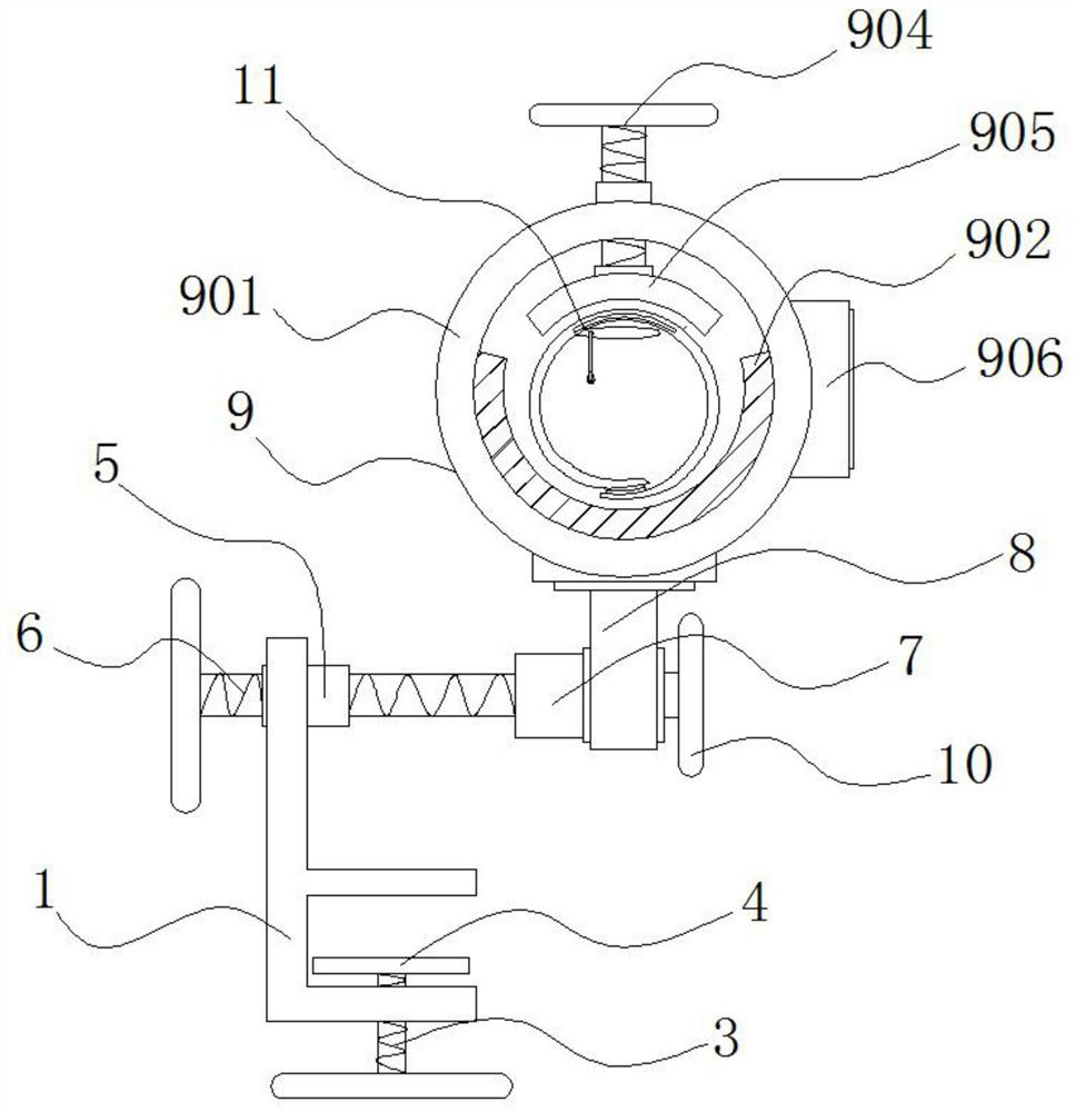
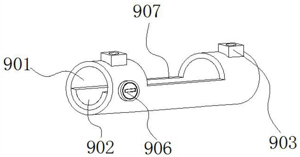
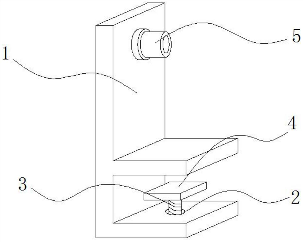
The invention discloses an auxiliary stent for puncture, and relates to the technical field of auxiliary stents for medical hemostatic balloons. Specifically, the auxiliary stent comprises a clampingplate, a fixed tube sheet and a hemostatic balloon, wherein a first threaded mouth is formed in the bottom of the clamping plate, a first threaded rod penetrates the interior of the first threaded mouth, and a fixing clamping plate is connected to the top of the first threaded rod; a second threaded mouth is formed in the top of the clamping plate, a second threaded rod penetrates the interior ofthe second threaded mouth, and a bearing is connected to the inner end of the second threaded rod; and the fixed tube sheet is fixed to the top of a connecting piece, and the hemostatic balloon is arranged inside the fixed tube sheet. According to the auxiliary stent for puncture, a lower pressing plate can be lifted vertically so as to adjust the distance between the lower pressing plate and thebottom of the inner wall of an arm placing tube, arms of different thickness and size can be clamped conveniently through the arrangement, an observation skylight is formed in the middle of the arm placing tube, the observation skylight can be used for observing the situation of the puncture site of the arms in real time, and meanwhile air circulation inside the arm placing tube can be maintainedconveniently.

Description

technical field [0001] The invention relates to the technical field of medical hemostatic balloon auxiliary bracket, in particular to an auxiliary bracket for puncture. Background technique [0002] Wristband-type hemostatic airbag for puncture is to wear the hemostatic airbag on the patient's wrist, wrap around the puncture point, make the airbag stick to the medical gauze and press the medical gauze on the puncture site, so as to closely fit the puncture site, and pass to the hemostasis Gas is injected into the airbag to strengthen the tightness between the medical gauze and the puncture site, so as to achieve the effect of compression and hemostasis. [0003] The existing wristband-type hemostatic airbag is worn on the patient's wrist in the form of a watch. Although it has a hemostatic effect, some patients have poor compliance and cannot brake the wrist, which is prone to excessive limb movement. Excessive activity affects the prognosis of the puncture site, especially...

Claims


Application Information

Patent Timeline
IPC IPC(8): A61B17/12A61G7/075
CPCA61B17/12A61B2017/12004A61G7/075
Inventor 孙利平
Owner 孙利平
Learn More