
Active storage type stretcher for emergency treatment of emergency department

An active and emergency technology, applied in the field of stretchers, can solve the problems of high effort, secondary injury to the patient, labor consumption, etc., to save effort, avoid displacement, and ensure stability.

Active Publication Date: 2020-09-15
THE AFFILIATED HOSPITAL OF QINGDAO UNIV
View PDF11 Cites 5 Cited by
  • Summary
  • Abstract
  • Description
  • Claims
  • Application Information

AI Technical Summary

Problems solved by technology

[0006] In order to overcome the shortcomings of the existing method, which requires a lot of effort to operate, easily causes the bed to shake, causes secondary injury to the patient, and consumes manpower during operation, the technical problem to be solved by the present invention is to provide a It is more convenient to put away the stretcher, can ensure the stability of the hospital bed, thereby ensuring the safety of workers, and saves manpower for the active storage stretcher for emergency department first aid.

Method used


Image

  • Active storage type stretcher for emergency treatment of emergency department
  • Active storage type stretcher for emergency treatment of emergency department
  • Active storage type stretcher for emergency treatment of emergency department

Examples


Embodiment 1

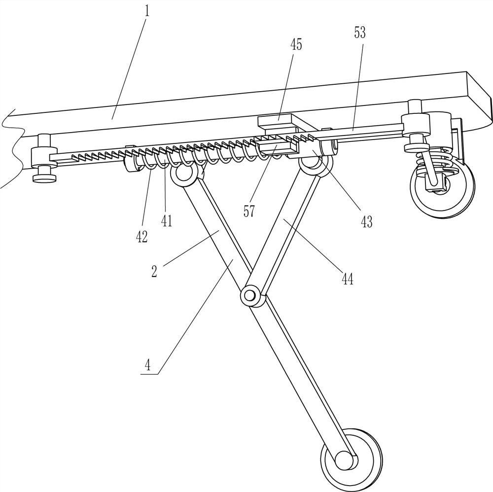
[0027] An active storage type stretcher for first aid in emergency department, such as figure 1 , figure 2 , image 3 and Figure 6 As shown, it includes a long board 1, a hinged rod 2 and a roller 3. Two hinged rods 2 are hingedly connected to the left and right sides of the bottom of the long board 1. The bottom end of the hinged rod 2 is rotatably connected to a roller 3, and a folding mechanism is also included. 4 and a locking mechanism 5, a folding mechanism 4 is provided between the long board 1 and the hinge rod 2, and a locking mechanism 5 is provided between the long board 1 and the folding mechanism 4.

[0028] The folding mechanism 4 includes a guide rod 41, a first spring 42, a guide sleeve 43, a connecting rod 44 and a horizontal plate 45. Two guide rods 41 are connected to the left and right sides of the bottom of the long board 1, and the two guide rods 41 are arranged front and back. A guide sleeve 43 is slidably connected to the guide rod 41, a first spri...

Embodiment 2

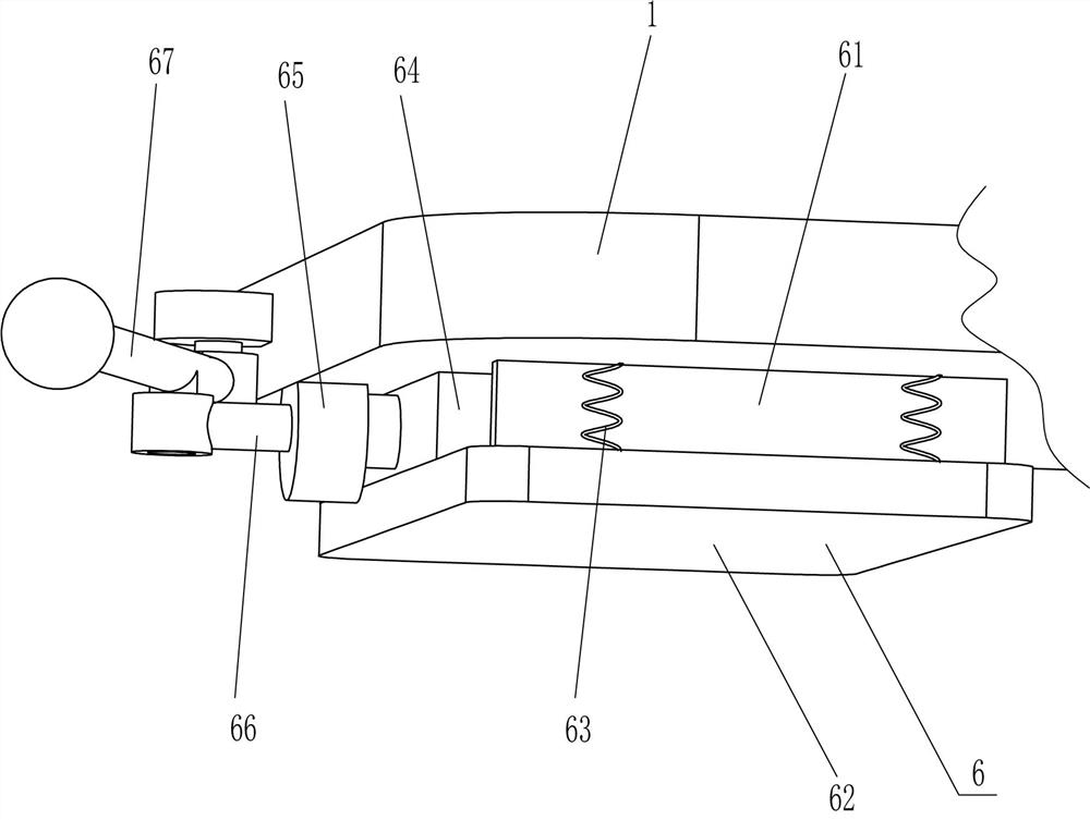
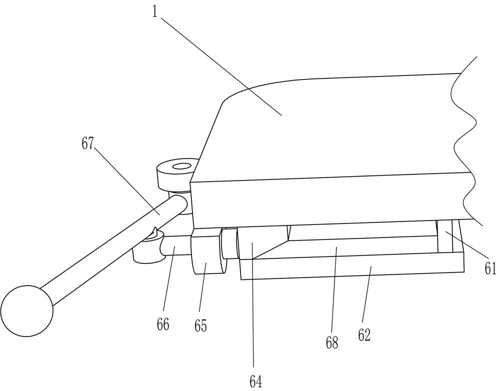
[0032] On the basis of Example 1, such as Figure 4-5 As shown, a stabilizing mechanism 6 is also included, and the stabilizing mechanism 6 includes a guide frame 61, a friction plate 62, a third spring 63, a wedge block 64, a second sliding sleeve 65, a second sliding rod 66, a lever 67 and an oblique plate 68. A guide frame 61 is connected to the left side of the bottom of the long plate 1. A slanted plate 68 is slidably connected to the guide frame 61. A friction plate 62 is connected to the bottom of the slanted plate 68. A second friction plate 62 is connected to the long plate 1. Three springs 63, the left side of the bottom of the long board 1 is connected with a second sliding sleeve 65, the second sliding sleeve 65 is slidingly connected with a second slide bar 66, and the right end of the second slide bar 66 is connected with a wedge block 64, and the wedge block 64 and The slanted plate 68 contacts, and the left side of the long board 1 is hingedly connected with a ...


PUM


Abstract

The invention relates to a stretcher, in particular to an active storage type stretcher for emergency treatment of the emergency department. The technical problem to be solved by the invention is howto design an active storage type stretcher, which is more convenient to unfold and fold and can guarantee stability of a sickbed, protects safety of works and save manpower, for emergency treatment ofthe emergency department. The active storage type stretcher for emergency treatment of the emergency department comprises a long plate, a folding mechanism and a locking mechanism; two hinge rods arehinged to two sides of the bottom of the long plate, and rollers are rotatably connected to the tail ends of the hinge rods; the folding mechanism is arranged between the long plate and the hinge rods; and the locking mechanism is arranged between the long plate and the folding mechanism. The folding mechanism and the locking mechanism are matched to assist in folding and unfolding the stretcher,so that the effect of folding and unfolding the stretcher is achieved.

Description

technical field [0001] The invention relates to a stretcher, in particular to an active storage type stretcher for first aid in the emergency department. Background technique [0002] The stretcher equipped in the ambulance meets the needs of the condition and is convenient for the patient and the wounded to lie down. Due to the heavy weight of the stretcher itself, it is laborious to carry it. Stretchers are divided into lifting stretchers, wheel stretchers, scoop stretchers, negative pressure inflatable cushion fixed stretchers, basket stretchers and roll stretchers according to the use method. [0003] At present, when the stretcher is getting on and off the ambulance, the outriggers of the stretcher need to be unfolded and put away manually. Because it is inconvenient to manually unfold and put away the outriggers of the stretcher, it takes a lot of effort and it is easy to cause the bed to shake. Thereby cause secondary injury to patient, and comparatively consume man...

Claims


Application Information

Patent Timeline
IPC IPC(8): A61G1/013A61G1/02A61G1/04A61G1/056
CPCA61G1/013A61G1/02A61G1/04A61G1/0562A61G2203/70A61G2220/14
Inventor 陈韩
Owner THE AFFILIATED HOSPITAL OF QINGDAO UNIV
Learn More