
Nursing transfer bed for department of cardiology

A transfer bed and cardiology technology, applied in medical transportation, transportation and packaging, vehicle rescue, etc., can solve the problems of inconvenient transfer of patients to the operating bed, prone to danger, and fixed patients, so as to eliminate arrhythmia, The effect of avoiding danger and avoiding secondary injury

Active Publication Date: 2020-09-15
临沂未来科技城开发建设集团有限公司
View PDF9 Cites 2 Cited by
  • Summary
  • Abstract
  • Description
  • Claims
  • Application Information

AI Technical Summary

Problems solved by technology

Most of the existing multi-functional cardiology nursing transfer beds have complex structures and troublesome operations, and patients cannot be easily transferred to the operating bed, and patients cannot be fixed during the transfer process, which is poor in safety and prone to danger. Medical patients need to be equipped with emergency treatment equipment to reduce the risk when they are transferred, and the patient needs to be protected during the transfer to reduce the shaking of the patient

Method used


Image

  • Nursing transfer bed for department of cardiology
  • Nursing transfer bed for department of cardiology
  • Nursing transfer bed for department of cardiology

Examples


Embodiment 1

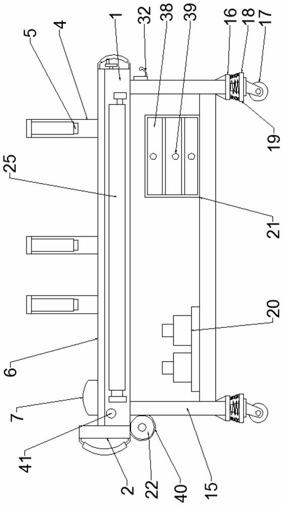
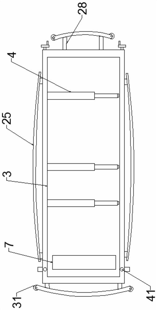
[0026] like Figure 1-7 As shown, the cardiology care transfer bed according to the embodiment of the present invention includes a bed frame 1, the middle part of the bed frame 1 is a groove structure, and a top plate 2 is arranged on the top of one end of the bed frame 1, and the bed frame 1 The middle part of the upper end groove is provided with a bed board 3, and the side of the bed board 3 is provided with several straps 4, and one end of the straps 4 is provided with buckles 5, and the upper end of the bed board 3 is provided with a cotton pad 6, The upper side of the cotton pad 6 is provided with a pillow 7, and both sides of the bed frame 1 are provided with an adjustment device that is matched with the bed board 3, and the adjustment device includes an inner upper end of the bed frame 1. The threaded screw 8, one end of the threaded screw 8 extends to one end of the bed frame 1 is provided with an adjustment handle 9, the threaded screw 8 is located inside the bed fra...

Embodiment 2

[0029] like Figure 1-6 As shown, the adjusting handle 9 is provided with a non-slip sleeve. The upper end of the bed frame 1 and the upper end of the screw rod 8 are provided with a reel 23 , and a telescopic curtain 24 is provided between the reel 23 and the side of the bed board 3 . It is not difficult to see from the above design that by setting the telescopic curtain 24 under the reel 23 to stretch along with the lifting of the bed board 3, and effectively expand and contract on the reel 23, it is ensured that the telescopic curtain 24 is tensioned during the lifting of the bed board 3 To achieve the separation of the bed board 3 and the bed frame 1 gap to the side, the telescopic curtain 24 can effectively prevent the patient's hand clothes and other items from falling into the gap between the bed board 3 and the bed frame 1.

[0030] like Figure 1-6 As shown, both ends of the bed frame 1 are provided with anti-collision arc beams 25, both ends of the bed frame 1 are ...


PUM


Abstract

The invention discloses a nursing transfer bed for the department of cardiology. A plurality of bandages are arranged on the side edge of a bed plate; a buckle is arranged at one end of each bandage;a cotton cushion is arranged at the upper end of the bed plate; a pillow is arranged on one side of the upper end of the cotton cushion; adjusting devices connected with the bed plate in a matched mode are arranged on the two sides of a bed frame; universal wheels are arranged at the lower end of a bottom plate; connecting plates are arranged at the upper ends of the universal wheels; a damping device is arranged between each connecting plate and the bottom plate; a fixing plate is arranged between the middles of supporting columns; a cardiac defibrillator is arranged on one side of the upperend of the fixing plate; a containing box is arranged at the side, away from the cardiac defibrillator, of the upper end of the fixing plate, and a breathing machine is arranged at the side, close tothe supporting columns, of the lower end of the bed frame. The nursing transfer bed has the advantages of being beneficial to rehabilitation of a patient, more convenient to use and high in practicability.

Description

technical field [0001] The invention relates to the technical field of medical cardiology, in particular to a nursing transfer bed for cardiology. Background technique [0002] The Department of Cardiology, that is, the Department of Cardiovascular Medicine, is a clinical department set up by the major internal medicine departments of hospitals at all levels for the diagnosis and treatment of cardiovascular and vascular diseases. The diseases treated include angina pectoris, hypertension, sudden death, arrhythmia, heart failure, premature beats, arrhythmia, Myocardial infarction, cardiomyopathy, myocarditis, acute myocardial infarction and other cardiovascular diseases. Most of the existing multifunctional cardiology nursing transfer beds have complex structures and troublesome operations, and cannot conveniently transfer patients to the operating bed, and cannot fix the patients well during the transfer process, which is poor in safety and prone to danger. Medical patients...

Claims


Application Information

Patent Timeline
Patent Type & Authority Applications(China)
IPC IPC(8): A61G1/02A61G1/04A61G1/044A61B90/14
CPCA61G1/02A61G1/04A61G1/044A61B90/14A61G2203/72A61G2203/723
Inventor 不公告发明人
Owner 临沂未来科技城开发建设集团有限公司
Learn More