
Corner combining machine for curtain wall door and window machining

A technology for corner forming machines and doors and windows, which is applied in metal processing equipment, manufacturing tools, feeding devices, etc., can solve the problems of cumbersome use by operators, lower product standards, and inconvenience in aluminum alloy processing, so as to improve the competitiveness of enterprises and improve product quality. The effect of high quality and product standards

Active Publication Date: 2020-09-15
诸暨市鑫海纺织服饰有限公司
View PDF4 Cites 10 Cited by
  • Summary
  • Abstract
  • Description
  • Claims
  • Application Information

AI Technical Summary

Problems solved by technology

[0004] 1. The existing device has a poor effect on adjusting the bending angle, and it is not convenient for the operator to process aluminum alloys with different angles, which makes the operation more cumbersome for the operator;
[0005] 2. When the existing device is processing the material to be processed, the effect of clamping and fixing is poor, and it is not convenient for the operator to process;
[0006] 3. The effect of limiting the shape of the splint in the corner forming machine is poor, and deviations are prone to occur, which in turn reduces the product standard, making the product quality uneven, and it is difficult to effectively improve the competitiveness of enterprises

Method used


Image

  • Corner combining machine for curtain wall door and window machining
  • Corner combining machine for curtain wall door and window machining
  • Corner combining machine for curtain wall door and window machining

Examples


Embodiment Construction

[0037] The technical solutions of the present invention will be further described below in conjunction with the accompanying drawings and through specific implementation methods.

[0038] Wherein, the accompanying drawings are only for illustrative purposes, showing only schematic diagrams, rather than physical drawings, and should not be construed as limitations on this patent; in order to better illustrate the embodiments of the present invention, some parts of the accompanying drawings will be omitted, Enlargement or reduction does not represent the size of the actual product; for those skilled in the art, it is understandable that certain known structures and their descriptions in the drawings may be omitted.

[0039] In the drawings of the embodiments of the present invention, the same or similar symbols correspond to the same or similar components; , "inner", "outer" and other indicated orientations or positional relationships are based on the orientations or positional ...


PUM


Abstract

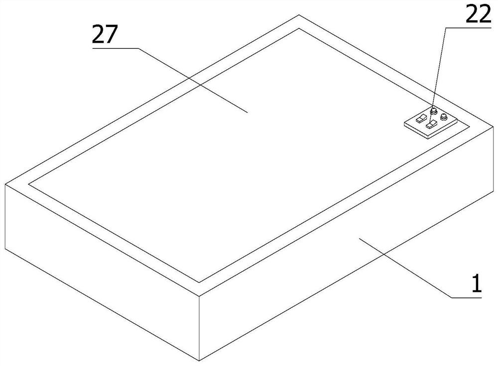
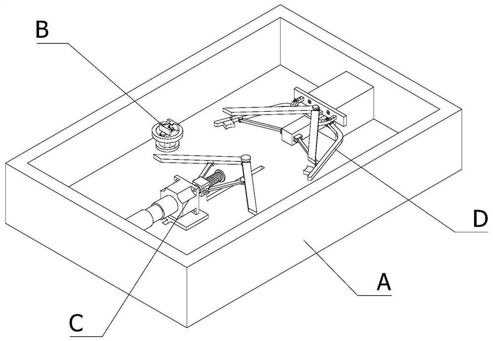
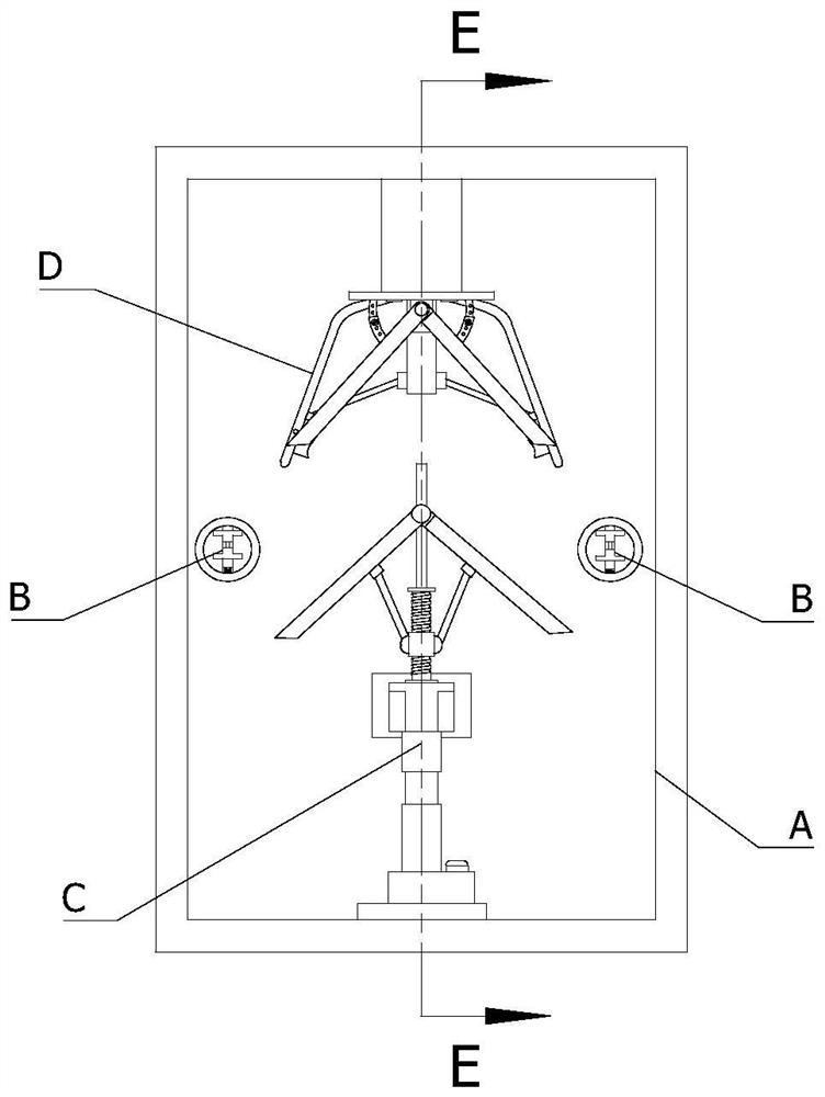
The invention relates to the field of corner combining machines, in particular to a corner combining machine for curtain wall door and window machining. The corner combining machine comprises a closedworking bin, fixers, a bending mechanism, a shape correcting mechanism and a controller, wherein the fixers, the bending mechanism and the shape correcting mechanism are all installed in the closed working bin, the two fixers are arranged on the two sides of the closed working bin in the width direction, the bending mechanism is provided with a first working end and a second working end which arematched with each other, the first working end and the second working end are arranged on the two sides in the length direction of the closed working bin correspondingly and are oppositely arranged,the shape correcting mechanism is arranged under the second working end, and the controller is electrically connected with the bending mechanism and the shape correcting mechanism. According to the corner combining machine, the bending angle can be adjusted, bent clamping rods can be limited, errors are prevented, and aluminum alloy needing to be treated can be clamped.

Description

technical field [0001] The invention relates to the field of corner forming machines, in particular to a corner forming machine for curtain wall, door and window processing. Background technique [0002] The corner forming machine is a special equipment for the production of high-grade broken bridge aluminum alloy doors and windows. It is suitable for the angle connection of aluminum doors and windows with corner code structure. Corner machine, the corner slide is driven by the corner cylinder, the corner slide moves forward, and the left and right punching shafts are pushed at the same time, and the corner knives on the punching shaft realize the angle connection of aluminum doors and windows; [0003] Existing existing following shortcomings: [0004] 1. The existing device has a poor effect on adjusting the bending angle, and it is not convenient for the operator to process aluminum alloys with different angles, which makes the operation more cumbersome for the operator;...

Claims


Application Information

Patent Timeline
Patent Type & Authority Applications(China)
IPC IPC(8): B21D7/022B21D7/16B21D3/00B21D43/00
CPCB21D7/022B21D7/16B21D3/00B21D43/003
Inventor 蒋炉军
Owner 诸暨市鑫海纺织服饰有限公司
Learn More