Charging head anti-dragging structure for charging pile

A charging pile and charging head technology, which is applied in charging stations, electric vehicle charging technology, electric vehicles, etc., can solve problems such as dragging and tearing of the connecting wire of the charging head, reducing the service life of the charging head, and damage to the charging pile. , to achieve the effect of easy plugging and unplugging, increasing design rationality and avoiding falling

Pending Publication Date: 2020-09-15
王敏敏
View PDF4 Cites 5 Cited by
  • Summary
  • Abstract
  • Description
  • Claims
  • Application Information

AI Technical Summary

Problems solved by technology

[0003] In the existing technology, the charging head of most charging piles on the market lacks corresponding anti-drag measures. Once the charging pile is used up, once the user forgets to unplug the charging head from the charging device, when the charging device leaves, the charging device will The charging head and charging cable on the charging pile will be dragged. If the user cannot find and remove the charging head in time, it is easy to cause the cable of the charging head to be dragged and broken, which greatly reduces the use of the charging head. In severe cases, the charging pile will be damaged by pulling. For this reason, we propose an anti-drag structure for the charging head of the charging pile.

Method used


Image

  • Charging head anti-dragging structure for charging pile
  • Charging head anti-dragging structure for charging pile
  • Charging head anti-dragging structure for charging pile

Examples


Embodiment Construction

[0031] The technical solutions of the present invention will be clearly and completely described below in conjunction with the embodiments. Apparently, the described embodiments are only some of the embodiments of the present invention, not all of them. Based on the embodiments of the present invention, all other embodiments obtained by persons of ordinary skill in the art without creative efforts fall within the protection scope of the present invention.

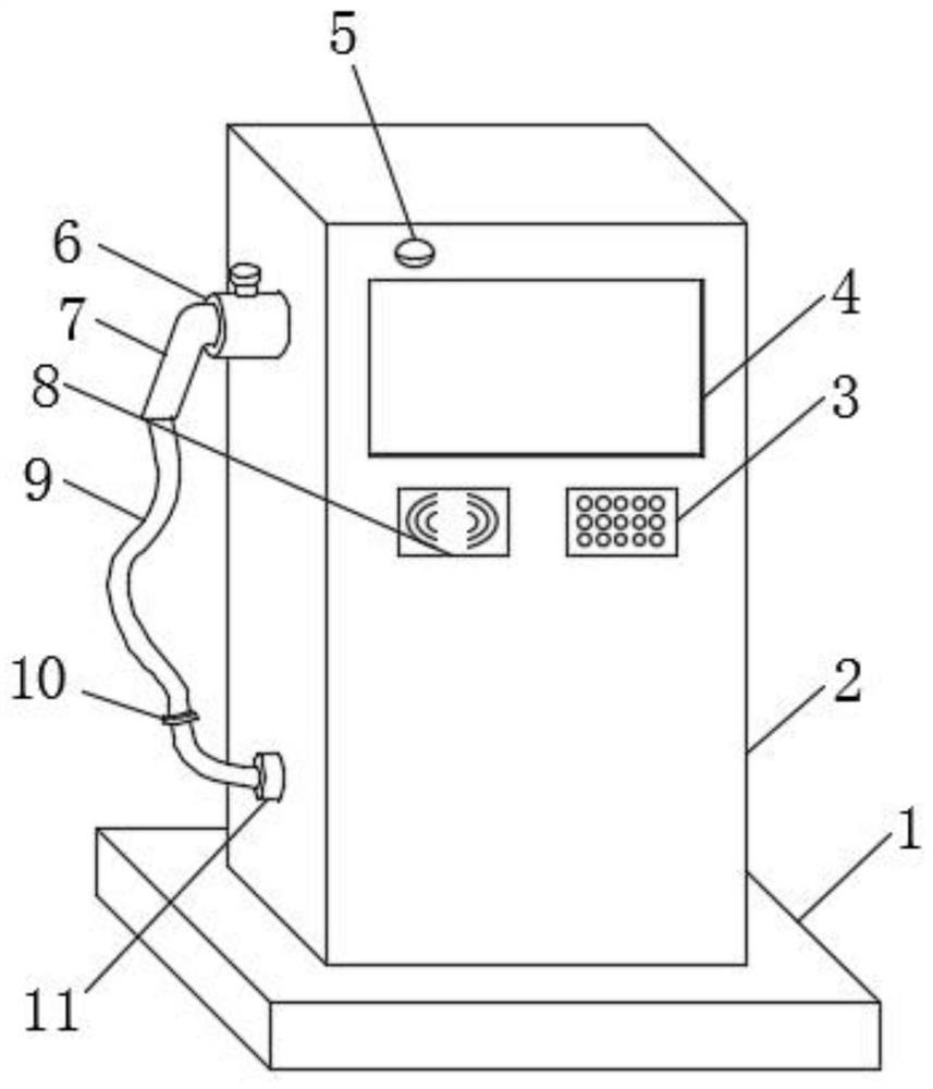
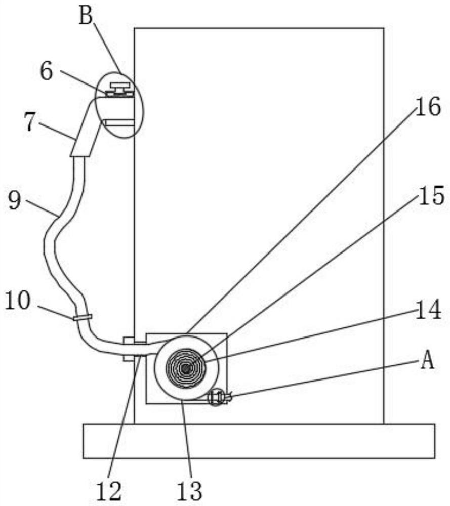
[0032] Such as Figure 1-Figure 4 As shown, a charging head anti-drag structure for a charging pile includes a base 1, a charging pile main body 2, a keypad 3, a display screen 4, a hanging block 6, a charging head 7, a card swiping area 8, and a charging line 9. The base 1 is installed on the lower side of the pile main body 2, the display screen 4 is installed on the front side of the charging pile main body 2, the card swiping area 8 is installed on the lower side of the display screen 4, and the key board is installed o...


PUM


Abstract

The invention provides a charging head anti-dragging structure for a charging pile. The structure comprises an alarm, a water blocking ring, a wire passing hole, a winding ring, a clockwork spring, anaxis rod, a containing cavity, a wire clamping hoop, an anti-dragging ring, a clamping plate and a pull rod; the water blocking ring is installed on the lower side of a hanging block and located on one side face of a charging pile body; the wire passing hole is formed in one side of the water blocking ring and located in the charging pile body; a charging wire penetrates through the water blocking ring and the wire passing hole in sequence; the alarm is assembled on the front side of the charging pile body and located on the upper side of a display screen; the containing cavity is formed in the charging pile body; the axis rod is mounted in the containing cavity; the clockwork spring is fixedly mounted on the annular side surface of the axis rod; the winding ring is fixedly installed on the outer side of the clockwork spring; the wire clamping hoop is installed in the containing cavity; the anti-dragging ring is installed in the containing cavity and located on the charging wire; andthe clamping plate is installed in a movable cavity; and the pull rod is installed on the upper side of the clamping plate. The structure is reasonable, a user is conveniently reminded to drag a charging head, and the charging head is effectively prevented from being damaged.

Description

technical field [0001] The invention belongs to the technical field of charging pile applications, and relates to an anti-drag structure for a charging head, in particular to an anti-drag structure for a charging head for a charging pile. Background technique [0002] The function of the charging pile is similar to the refueling machine in the gas station. It can be fixed on the ground or wall, and installed in public buildings (public buildings, shopping malls, public parking lots, etc.) and residential area parking lots or charging stations. Charge all models of electric vehicles. The input end of the charging pile is directly connected to the AC grid, and the output end is equipped with a charging plug for charging the electric vehicle. Charging piles generally provide two charging methods: conventional charging and fast charging. People can use a specific charging card to swipe the card on the human-computer interaction interface provided by the charging pile to perform...

Claims


Application Information

Patent Timeline
Patent Type & Authority Applications(China)
IPC IPC(8): B60L53/31B60L53/16G08B21/24B60L53/18
CPCB60L53/31B60L53/16G08B21/24B60L53/18Y02T10/70Y02T10/7072Y02T90/12Y02T90/14
Inventor 王敏敏
Owner 王敏敏
Why Eureka
Try Eureka