Positioning and mounting structure for rear auxiliary frame of electric vehicle

A technology of rear subframe and installation structure, which is applied in the direction of the connection between the upper structure, the lower structure and the sub-assembly of the upper structure, to achieve the effect of enhancing the local rigidity and strength, reducing the difficulty of installation and simplifying the installation process

Active Publication Date: 2020-09-15
ZHEJIANG LEAPMOTOR TECH CO LTD
View PDF11 Cites 2 Cited by
  • Summary
  • Abstract
  • Description
  • Claims
  • Application Information

AI Technical Summary

Problems solved by technology

[0004] In order to overcome the rear drive arrangement of electric vehicle motors in the prior art, the present invention has higher requirements for structural strength, rigidity and durability than traditional vehicles for the installation point of the vehicle body, and higher requirements for installation accuracy. Problems that cannot meet the above requirements, provide a rear sub-frame positioning and installation structure for electric vehicles, improve the installation and positioning accuracy between the body and rear sub-frame, simplify the installation process, and improve the overall rigidity and strength

Method used


Image

  • Positioning and mounting structure for rear auxiliary frame of electric vehicle
  • Positioning and mounting structure for rear auxiliary frame of electric vehicle
  • Positioning and mounting structure for rear auxiliary frame of electric vehicle

Examples


Embodiment

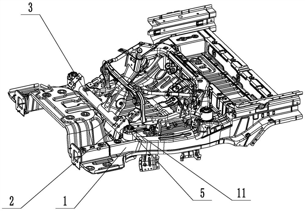
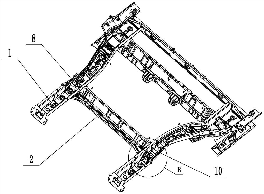
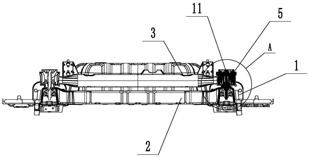
[0025] Such as figure 1 , figure 2 with image 3 As shown, a rear sub-frame positioning and installation structure of an electric vehicle includes a rear longitudinal beam 1, a rear cross beam 2, a rear sub-frame 3, a U-shaped reinforcement 6, a middle support 7, a box-shaped reinforcement plate 8 and a longitudinal The beam reinforcement plate 10, the two ends of the rear cross beam 2 are respectively fixed to the rear longitudinal beam 1 on both sides, and the two joints of the rear cross beam 2 and the rear longitudinal beam 1 are each provided with a positioning connecting pipe 4, such as Figure 4 As shown, the positioning connecting pipe 4 is provided with a positioning counterbore 4.1, and the bottom surface of the positioning counterbore 4.1 is provided with a connecting threaded hole 4.2, and each side of the rear subframe 3 is provided with a positioning bushing 5, and one of the positioning bushings 5 The outer contour of the positioning boss 5.1 on the top is ci...


PUM


Abstract

The invention discloses a positioning and mounting structure for a rear auxiliary frame of an electric vehicle. The structure comprises rear longitudinal beams, a rear cross beam and a rear auxiliaryframe; two ends of the rear cross beam are respectively fixed with the rear longitudinal beams on two sides; a positioning connecting pipe is arranged at the joint of the rear cross beam and the rearlongitudinal beams; a positioning counter bore is formed in the positioning connecting pipe; a connecting threaded hole is formed in the bottom face of the positioning counter bore; a positioning bushing is arranged on the rear auxiliary frame; the positioning bushing is fixed to the rear auxiliary frame; the positioning bushing is provided with a positioning boss; a through hole is formed in thepositioning bushing; the through hole penetrates through the positioning bushing and the positioning boss; the positioning boss is matched with the positioning counter bore; and a mounting bolt penetrates through the through hole to be connected with the connecting threaded hole. With the positioning and mounting structure for the rear auxiliary frame of the electric vehicle of the invention adopted, the mounting and positioning precision between a vehicle body and the rear auxiliary frame is improved, a mounting process is simplified, and overall rigidity and strength are improved.

Description

technical field [0001] The invention relates to the field of electric vehicle manufacturing, in particular to a rear auxiliary frame positioning and installation structure of the electric vehicle. Background technique [0002] In the development process of the electric vehicle body structure, the motor rear drive arrangement is more and more common. The rear subframe is an important load-bearing part of the electric vehicle rear drive arrangement, and its installation point with the vehicle body has higher requirements for structural strength, stiffness and durability. Traditional vehicles have higher requirements, and at the same time have higher requirements for installation accuracy, and their structural design has also become the focus of engineering solutions. Therefore, it is necessary to design a positioning and installation structure for the rear subframe of the electric vehicle, which can improve the installation accuracy and reduce the positioning tooling of the fi...

Claims


Application Information

Patent Timeline
Patent Type & Authority Applications(China)
IPC IPC(8): B62D21/02B62D27/02
CPCB62D21/02B62D27/023
Inventor 陈智家齐鲁杰郭大洲
Owner ZHEJIANG LEAPMOTOR TECH CO LTD
Why Eureka
Try Eureka