

Substrate fastening structure, optical scanning device, and image forming apparatus
- Summary
- Abstract
- Description
- Claims
- Application Information
AI Technical Summary
Benefits of technology
Problems solved by technology
Method used
Image

Examples
embodiment 1
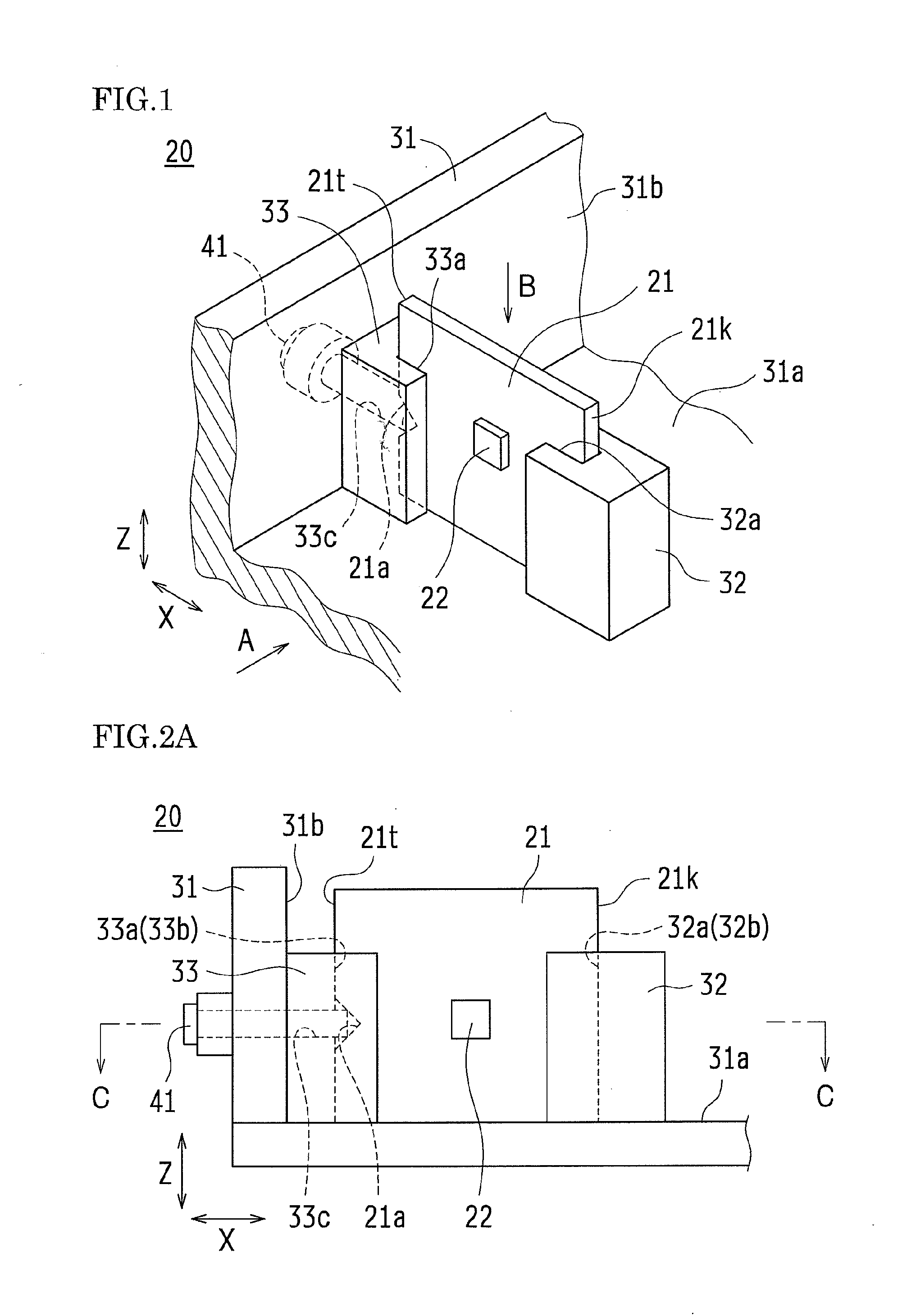
[0042]Hereinafter, description is given of a substrate fastening structure according to embodiment 1 of the present invention with reference to the accompanying drawings.
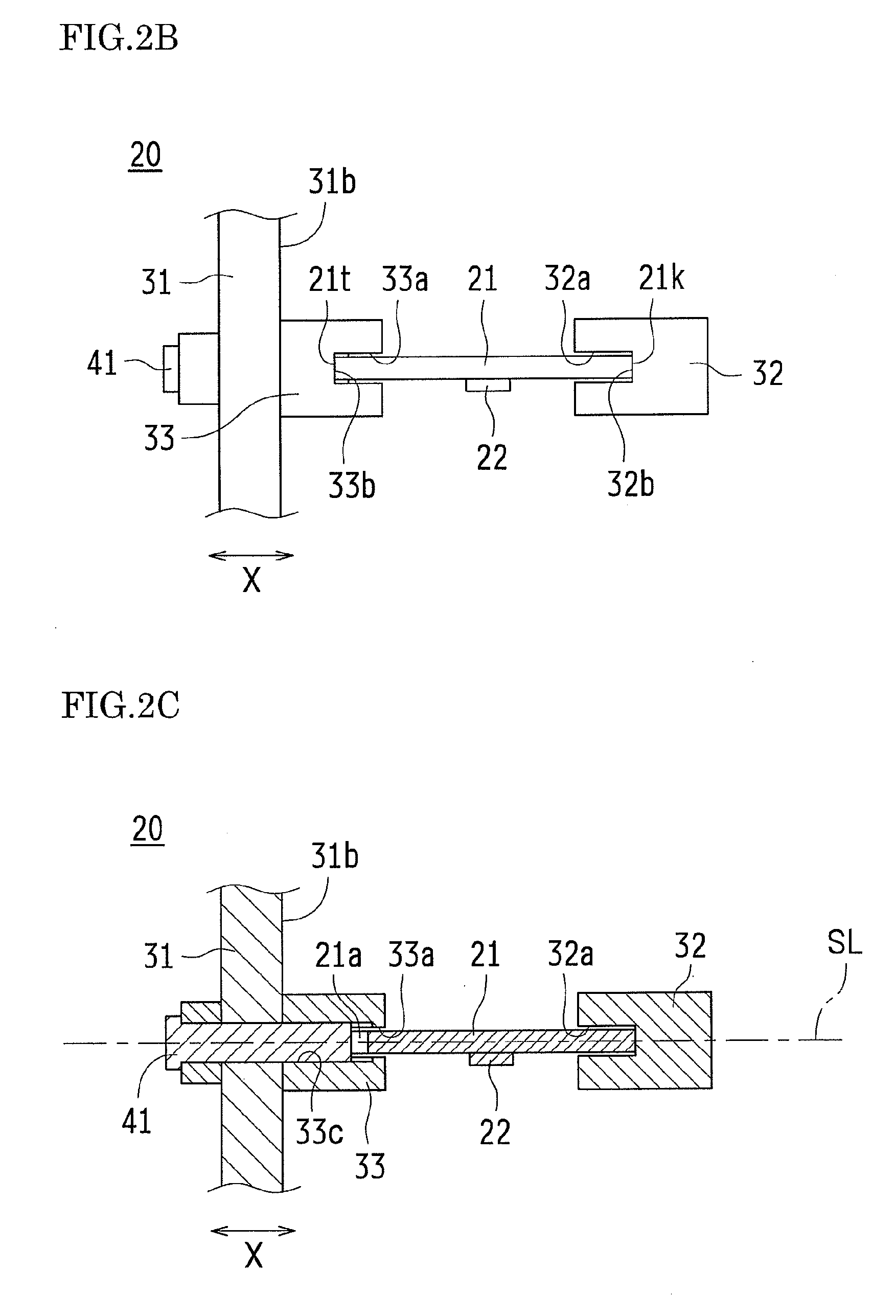
[0043]FIG. 1 is a principal component perspective view showing a portion of a substrate fastening structure according to embodiment 1 of the present invention. FIG. 2A is a principal component front view that shows a front surface of a substrate as a main part as viewed from an arrow A direction in FIG. 1. FIG. 2B is a principal component top view that shows a top surface of the substrate as a main part as viewed from an arrow B direction in FIG. 1. FIG. 2C is a principal component cross-sectional view through arrows C to C in FIG. 2A.
[0044]A substrate fastening structure 20 according to embodiment 1 of the present invention is provided with a substrate 21, in which an electronic component (for example, an optical detection sensor 22) is mounted, and a casing 31, to which the substrate 21 is secured internally. The ...
embodiment 2
[0066]FIG. 8 is an outline configuration drawing showing a configuration of an optical scanning device according to embodiment 2 of the present invention. It should be noted that same symbols are assigned and description is omitted in regard to configuration elements whose function and structure are essentially equivalent to those of embodiment 1.
[0067]In an optical scanning device 1 according to embodiment 2 of the present invention, a light source 1a, a collimator 1b, a concave lens 1c, an aperture 1d, a cylindrical lens 1e, an incident turning mirror 1f, a light polarizer 1g, a first scanning lens 1h, a second scanning lens 1j, an outgoing turning mirror 1k, and a cylindrical mirror 1m are arranged in order from upstream to downstream in the direction of advancement of a light BL irradiated from the light source 1a. It should be noted that the present invention is not limited to this and, for example, the order in which the second scanning lens 1j, the outgoing turning mirror 1k,...
embodiment 3
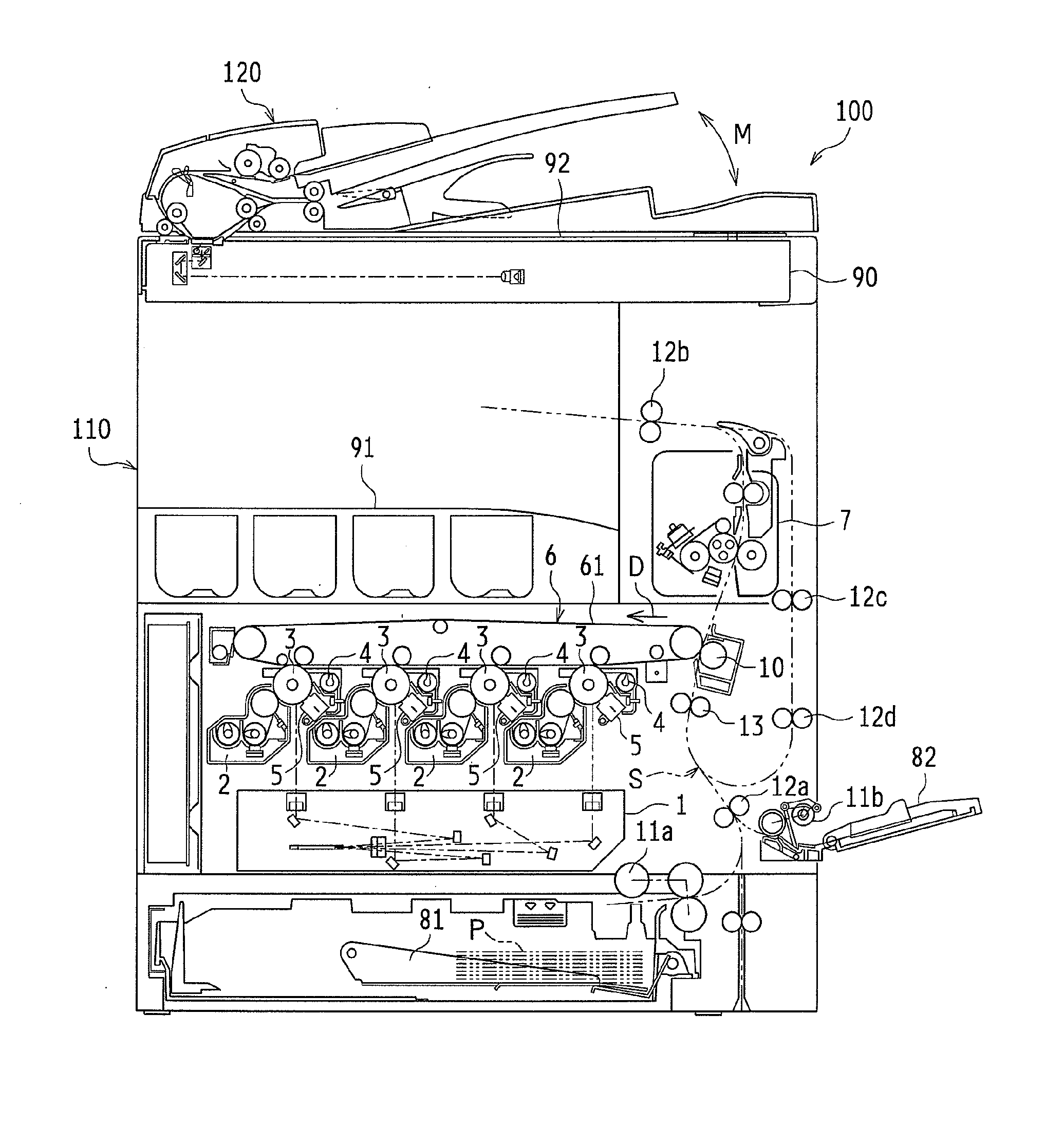
[0079]FIG. 9 is a lateral view showing an outline configuration of an image forming apparatus according to embodiment 3 of the present invention. It should be noted that same symbols are assigned and description is omitted in regard to configuration elements whose function and structure are essentially equivalent to those of embodiment 1 and embodiment 2.
[0080]An image forming apparatus 100 according to embodiment 3 of the present invention is provided with an apparatus main unit 110 and an automatic document processing device 120, and forms a multicolor or single color image on a predetermined paper (original) in response to image data transmitted from outside.
[0081]The apparatus main unit 110 is devised as a configuration provided with an optical scanning device 1, development devices 2, photosensitive drums 3, cleaning units 4, chargers 5, an intermediate transfer belt unit 6, and a fixing unit 7.
[0082]In addition to the above-mentioned configuration, the image forming apparatus ...
PUM
 Abstract
Description
Claims
Application Information