Tensioning end mechanism of linear cross belt sorting machine

A cross-belt sorting and straight-line technology, which is applied to conveyors, transportation and packaging, etc., can solve problems such as difficult operation, ground damage to equipment accuracy, and unusable shields, achieving high structural stability, less vibration and noise, and good synchronization effect

Pending Publication Date: 2020-09-15
ZHEJIANG DAMON TECH CO LTD
View PDF2 Cites 0 Cited by
  • Summary
  • Abstract
  • Description
  • Claims
  • Application Information

AI Technical Summary

Problems solved by technology

[0002] At present, there are many linear cross-belt sorters on the market that use rubber chain transmission. Because the rubber material is stretched under force, the rubber chain needs to be tensioned after a period of use. At present, the market is generally from There are many deficiencies in the overall movement of the moving end rack: 1. Since the rack has been fixed on the ground, the anchor bolts must be removed before adjustment, and new anchor bolts must be reinstalled after the adjustment is completed, causing damage to the ground and The impact of equipment accuracy; 2. The related shields cannot be used after the adjustment is completed, and it is labor-intensive and time-consuming to remake; 3. There is no roller support on the frame and the ground, and the resistance is large during adjustment, which is not easy to operate
[0004] The tensioning devices involved in the above-mentioned equipment have the aforementioned problems. In addition, there are many structural disadvantages in the overall movement of the rack to achieve chain tensioning.

Method used


Image

  • Tensioning end mechanism of linear cross belt sorting machine
  • Tensioning end mechanism of linear cross belt sorting machine
  • Tensioning end mechanism of linear cross belt sorting machine

Examples


Embodiment 1

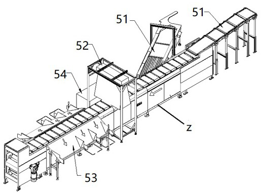
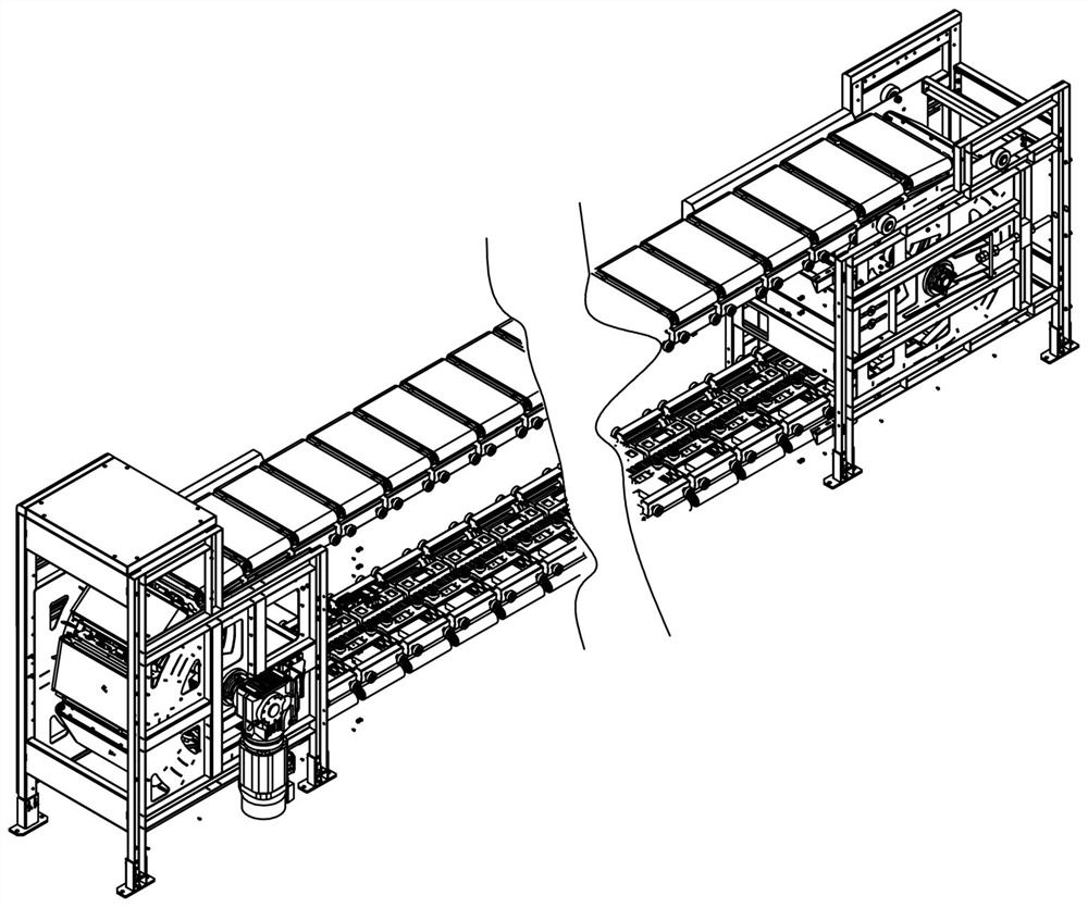
[0022] Example 1, such as Figure 1-17 As shown, a linear cross-belt sorter includes a driving end mechanism, a driven end mechanism, and a driving chain 1 connected between the driving end mechanism and the driven end mechanism, and also includes a driving chain 1 driven by the driving chain 1. Trolley a and trolley a are equipped with pallet belt conveyor b for sorting. Pallet belt conveyor b will be installed and connected to the top of the trolley. Pallet belt conveyor b is used to carry and sort goods. The conveying direction of pallet belt conveyor b follows The traveling direction of the trolley will cross, and it can be designed as a vertical cross conveyance like the existing ones. The driving end mechanism has a driving disc b1, and the driven end mechanism has a driven disc c1. The driving chain 1 is wound on the driving disc b1 and the driven disc c1 and forms a closed circuit that runs back and forth. The driven end mechanism is generally also called the tensionin...

Embodiment 2

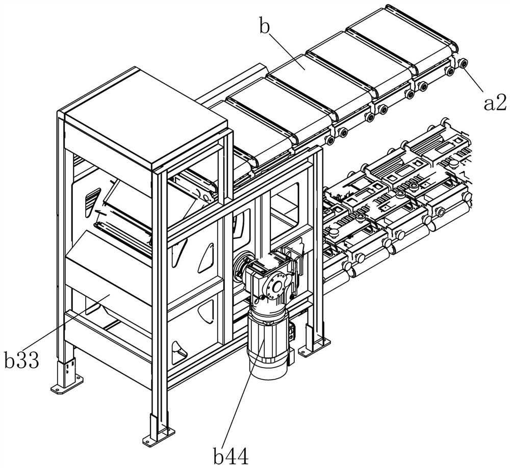
[0028] Embodiment 2, the drawings refer to Embodiment 1, a driving end mechanism of a linear cross-belt sorter, which can be used in the linear cross-belt sorter of Embodiment 1, mainly including the main motor shaft b41 and the main motor shaft The driving disc b1 for driving the driving chain 1 is installed on the b41, and the left and right sides of the driving disc b1 are fixedly connected with the main motor shaft b41 through the tensioning sleeve b42. The tension sleeve b42 is used to connect, compared with the flat key connection, the strength of torque transmission and impact load resistance is greatly enhanced.

[0029] Further, a tensioning sleeve b42 is respectively provided on both sides of the drive disc b1.

[0030] The left and right sides of the center hole of the driving disc b1 respectively extend to the left to form a left annular sleeve b11 and extend to the right to form a right annular sleeve b12, between the left annular sleeve b11 and the main motor sha...

Embodiment 3

[0040] Embodiment 3, the drawings refer to Embodiment 1, a tensioning end mechanism of a linear cross-belt sorter, which can be used in the linear cross-belt sorter implemented in 1, that is, as a driven end mechanism, mainly including The driven shaft c41 and the driven disc c1 installed on the driven shaft c41 for being driven by the drive chain 1 also includes a driven frame, and the driven frame includes an inner frame and an outer frame, The inner frame includes a left inner panel c31 and a right inner panel c32 which are arranged opposite to each other. The parts of the driven shaft c41 located on the left and right sides of the driven disc c1 are installed on the left inner panel c31 and the right inner panel c32 respectively. The outer frame includes a left outer frame c51 and a right outer frame c52 respectively provided on the left side of the left inner panel c31 and the right side of the right inner panel c32, the left inner panel c31 and the left outer frame c51 T...


PUM


Abstract

The invention relates to the technical field of logistics industry equipment, in particular to a tensioning end mechanism of a linear cross belt sorting machine. The tensioning end mechanism comprisesa driven shaft, a driven disc mounted on the driven shaft and used for being driven by a driving chain to operate and a driven frame comprising an inner frame and an outer frame, the inner frame comprises a left inner plate and a right inner plate which are oppositely arranged left and right, the parts, located on the left side and the right side of the driven disc, of the driven shaft are installed on the left inner plate and the right inner plate correspondingly, the outer frame comprises a left outer frame and a right outer frame which are arranged on the left side of the left inner plateand the right side of the right inner plate correspondingly, tensioning devices capable of being adjusted front and back are arranged between the left inner plate and the left outer frame and betweenthe right inner plate and the right outer frame, and adjustment is more convenient and reliable.

Description

technical field [0001] The invention relates to the technical field of logistics industry equipment, in particular to a tensioning end mechanism of a linear cross-belt sorter. Background technique [0002] At present, there are many linear cross-belt sorters on the market that use rubber chain transmission. Because the rubber material is stretched under force, the rubber chain needs to be tensioned after a period of use. At present, the market is generally from There are many deficiencies in the overall movement of the moving end rack: 1. Since the rack has been fixed on the ground, the anchor bolts must be removed before adjustment, and new anchor bolts must be reinstalled after the adjustment is completed, causing damage to the ground and The impact of equipment accuracy; 2. The related shields cannot be used after the adjustment is completed, and it is labor-intensive and time-consuming to remake; 3. There is no roller support on the frame and the ground, and the resistan...

Claims


Application Information

Patent Timeline
Patent Type & Authority Applications(China)
IPC IPC(8): B65G23/44B65G17/12B65G17/32B65G17/42B65G21/22B65G23/06B65G23/30
CPCB65G17/12B65G17/32B65G17/42B65G21/22B65G23/06B65G23/30B65G23/44
Inventor 李振刚谢振华
Owner ZHEJIANG DAMON TECH CO LTD
Why Eureka
Try Eureka