Anti-mist cooling tower and its anti-mist packing

A cooling tower and defogging technology, applied in the field of cooling towers, can solve the problems of unfavorable condensed water collection, poor defogging and water saving effect, etc., and achieve the goal of improving defogging and water saving effect, reducing pressure resistance and improving cooling capacity Effect

Active Publication Date: 2021-08-06
CHINA PETROLEUM & CHEM CORP +1
View PDF10 Cites 1 Cited by
  • Summary
  • Abstract
  • Description
  • Claims
  • Application Information

AI Technical Summary

Problems solved by technology

[0007] One object of the present invention is to provide a mist-eliminating cooling tower and its mist-eliminating filler, so as to improve the shortcomings of the existing mist-eliminating cooling towers that are unfavorable for condensed water collection and poor demisting and water-saving effects

Method used


Image

  • Anti-mist cooling tower and its anti-mist packing
  • Anti-mist cooling tower and its anti-mist packing
  • Anti-mist cooling tower and its anti-mist packing

Examples


Embodiment 1

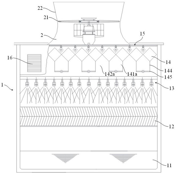
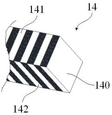
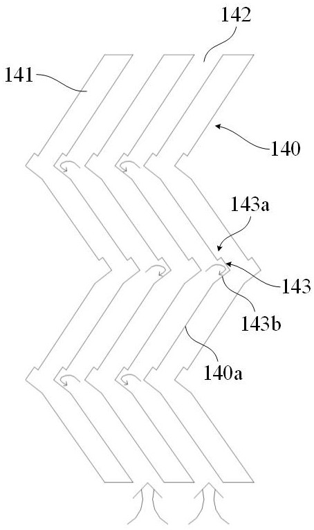
[0039] According to one or more embodiments of the present invention, with reference to Figure 1~Figure 3 As shown, the specific working process of the fog-eliminating cooling tower of the present invention is as follows (spring, autumn and winter), wherein the rotating baffle 145 is in the closed (horizontal) position, and the louvers 16 are opened.

[0040] The circulating hot water is evenly sprayed on the water-sprinkling filler 12 through the first sprayer 13, and the external dry and cold air, driven by the fan 21, enters from the air inlet (not shown in the figure) at the lower part of the tower body 1 and is sprayed. The water fill 12 flows upwards. The dry and cold air from the outside contacts with the circulating hot water sprayed by the first shower 13 above the water-spraying packing 12 in countercurrent, and transfers mass and heat on the surface of the water-spraying packing 12, and the circulating hot water is cooled and enters the bottom of the water-spraying...

Embodiment 2

[0044] In general, the anti-fog cooling tower needs to turn on the anti-fog function in spring, autumn and winter, and does not need anti-fog in summer. According to one or more embodiments of the present invention, with reference to Figure 2~Figure 4 Shown, the specific work process of the mist elimination cooling tower of the present invention in summer is as follows. Wherein the rotary shutter 145 is in the open position and the shutter 16 is closed.

[0045] The circulating hot water is evenly sprayed on the water-sprinkling filler 12 through the first sprayer 13, and the external dry and cold air, driven by the fan 21, enters from the air inlet (not shown in the figure) at the lower part of the tower body 1 and is sprayed. The water fill 12 flows upwards. The dry and cold air from the outside contacts with the circulating hot water sprayed by the first shower 13 above the water-spraying packing 12 in countercurrent, and transfers mass and heat on the surface of the wat...


PUM


Abstract

The invention discloses a mist-removing filler, which is composed of a plurality of heat exchange fins arranged, and a first channel and a second channel which are arranged at intervals and are not connected to each other are formed between the plurality of heat exchange fins. Each heat exchange fin includes: a plurality of baffle surfaces; a flow guide groove, which extends outward from the intersection of two adjacent baffle surfaces up and down, and the lower part of the flow guide groove forms a flow guide surface, and the flow guide The surface is deflected downward relative to the baffle surface below it; and the liquid collecting tank is surrounded by the upper part of the diversion groove and the deflecting surface above it, and the liquid collecting groove and the diversion groove above form a semi-closed diversion space. The invention also discloses a mist elimination cooling tower. The fog-eliminating cooling tower and its fog-eliminating filler of the present invention can more effectively capture the water mist in the hot and humid air through the cooperation of the diversion groove, the diversion surface and the liquid collection tank, and improve the effect of defogging and water saving.

Description

technical field [0001] The invention relates to the technical field of cooling towers, in particular to an anti-mist cooling tower and an anti-mist filler. Background technique [0002] In petroleum, chemical and other industries, circulating water cooling systems are widely built. Most circulating water cooling systems use open cooling towers as the main cooling equipment. The traditional open cooling tower uses filler to cool the circulating water. The circulating hot water from the process unit enters the cooling tower spray system and enters the filler from top to bottom. The filler is generally made of PVC sheet, and the water enters the filler to form water along the PVC sheet. The external dry and cold air enters the filler from bottom to top and exchanges heat with the water film. The water film evaporates and cools down. The air is heated and humidified to form hot and humid air. A fan is installed on the top of the cooling tower to discharge the hot and humid air ...

Claims


Application Information

Patent Timeline
Patent Type & Authority Patents(China)
IPC IPC(8): F28C1/16F28F25/08
CPCF28C1/16F28F25/08
Inventor 厉勇李晨光纪轩姜之宇徐佳斌王敬泽
Owner CHINA PETROLEUM & CHEM CORP
Why Eureka
Try Eureka