
Clinical ear washing device for otology

An otology and component technology, applied in ear treatment and other directions, can solve the problems of low work efficiency, the thickness of the patient's ear wall cannot be wiped dry, etc., and achieve the effect of convenient use

Active Publication Date: 2020-09-18
深圳市都市医药股份有限公司
View PDF9 Cites 4 Cited by
  • Summary
  • Abstract
  • Description
  • Claims
  • Application Information

AI Technical Summary

Problems solved by technology

[0005] In order to overcome the shortcomings of low work efficiency when cleaning the patient's ear wall and the inability to dry the patient's ear wall after cleaning, the technical problem is to provide a device that is convenient for people to use, has high work efficiency, and can dry the patient's ear after cleaning. Otology clinical ear washing device

Method used


Image

  • Clinical ear washing device for otology
  • Clinical ear washing device for otology
  • Clinical ear washing device for otology

Examples


Embodiment 1

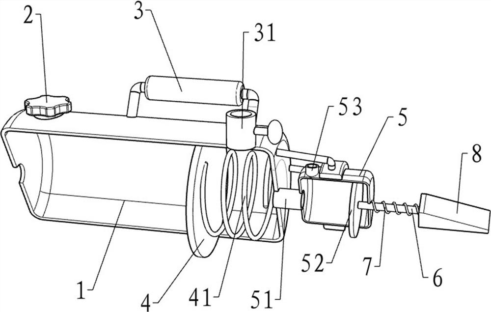
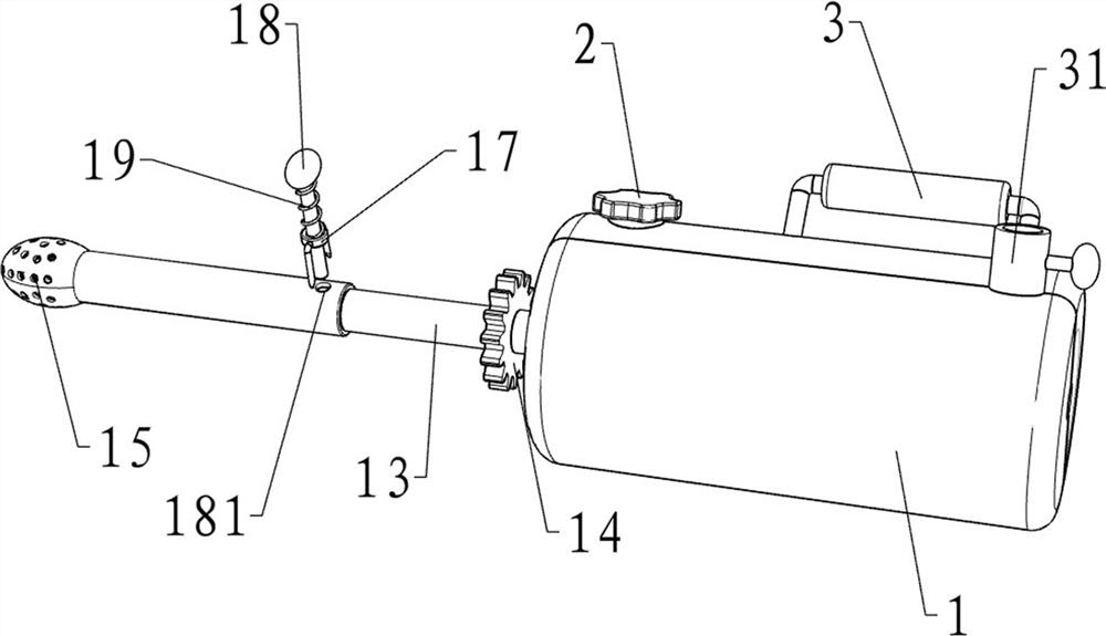
[0020] A kind of otological clinical earwashing device, such as Figure 1-4 As shown, it includes a water storage assembly, a power assembly, a cleaning assembly and a fixed assembly. The right side of the water storage assembly is provided with a power assembly that provides power through rotation, and the left side of the water storage assembly is provided with a cleaning assembly that is cleaned by rotation. As for the assembly, the cleaning assembly is provided with a fixing assembly fixed by pulling.

[0021] Such as Figure 1-4 As shown, the water storage assembly includes a water storage cylinder 1, a water inlet pipe 2, a handle 3, an air outlet pipe 31, a first piston 4 and a first spring 41, and the water inlet pipe 2 is welded on the left side of the top of the water storage cylinder 1, and the water storage cylinder A handle 3 is welded to the upper part of the rear side of the water cylinder 1, an air outlet pipe 31 with a valve is welded on the right side of the...

Embodiment 2

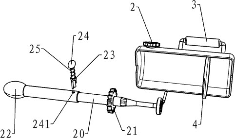
[0031] On the basis of Example 1, such as figure 1 with 4As shown, it also includes a telescopic rod 20, a second gear 21, a second sponge sleeve 22, a second guide sleeve 23, a second insertion rod 24 and a fourth spring 25, and the left part of the front side of the water storage cylinder 1 rotates through a bearing. The telescopic rod 20 is provided with a telescopic rod 20, the right side key of the telescopic rod 20 is connected with a second gear 21, the second gear 21 meshes with the column gear 12, the left end of the telescopic rod 20 is covered with a second sponge sleeve 22, and the telescopic rod 20 is provided with a second The guide sleeve 23, the second guide sleeve 23 is slidingly provided with a second insertion rod 24, a fourth spring 25 is wound between the second insertion rod 24 and the second guide sleeve 23, and the fourth spring 25 is in a stretched state. The telescopic rod 20 is provided with a second groove 241 , and the second groove 241 is matched...


PUM


Abstract

The invention relates to an ear washing device, and especially relates to a clinical ear washing device for otology. The technical problems to be solved are to provide the clinical ear washing devicefor otology which is convenient for people to use and high in working efficiency and can dry the ears of a patient. The ear washing device includes a water storage assembly, a power assembly, a cleaning assembly and a fixing assembly; the power assembly is installed on the water storage assembly and provides power through rotation; the cleaning assembly is installed on the water storage assembly and carries out cleaning through rotation; and the fixing assembly is installed on the cleaning assembly and carries out fixation through pulling. Water required during cleaning can be stored through the water storage assembly; power can be provided by the power assembly when the ear walls of the patient are cleaned; cleaning can be carried out on the ear walls of the patient through the cleaning assembly; fixing can be performed by the fixing assembly when equipment is adjusted to the proper length; and the ear walls of the patient can be dried through second sponge sleeves after being cleaned.

Description

technical field [0001] The invention relates to an ear washing device, in particular to an ear washing device for clinical otology. Background technique [0002] Ear cleaning is to wipe and clean the patient's ears before checking the ears, so that it is convenient for the staff to check the patient's ears. [0003] The patent application publication number CN110680611A discloses a clinical ear washing device for otology, which includes a box body, a liquid inlet mechanism, a liquid discharge mechanism, a cleaning mechanism, and a lithium battery. The clinical ear washing device for otology, Through the use of the device, the medical staff can absorb the cleaning solution from the atomized state to the sponge cover, so that the sponge cover in the rotating state and adsorbed with the cleaning solution can be rotated in the ear of the patient, so that the sponge The sleeve cleans the patient's ear wall. It can be seen that by using the device in this application, not only th...

Claims


Application Information

Patent Timeline
IPC IPC(8): A61F11/00
CPCA61F11/006
Inventor 不公告发明人
Owner 深圳市都市医药股份有限公司
Learn More