Cosmetic liquid stirrer

A technology for mixers and cosmetics, which is applied to mixers with rotating mixing devices, drives mixers to dissolve, mixers, etc., can solve problems such as affecting uniformity, low solubility of beeswax solid deposits, and easy splashing from the gap. , to achieve a strong effect of tightness

Inactive Publication Date: 2020-09-18
广州沐风信息科技有限公司
View PDF0 Cites 3 Cited by
  • Summary
  • Abstract
  • Description
  • Claims
  • Application Information

AI Technical Summary

Problems solved by technology

[0002] In the production process of cosmetics, it is necessary to stir the raw materials of cosmetics. The current cosmetic mixer relies on the stirring shaft for stirring. The stirring shaft of the cosmetic liquid has the function of stabilizing the speed. The beeswax in the cosmetic raw materials is in a solid state and has anti-bacterial function. , but when the cosmetic liquid is rotated and stirred, the high-speed rotation will form a swirl-like pattern, which will cause the cosmetic liquid to easily follow the direction of rotation, so that the cosmetic liquid will move synchronously with the stirring shaft along the edge of the mixing barrel, resulting in the same force direction, reducing the The stirring degree of the cosmetic liquid makes the effect of stirring and mixing unsatisfactory, resulting in a low degree of dissolution of the beeswax solid precipitate in the cosmetic liquid, and the cosmetic liquid will impact the upper end of the mixing barrel during synchronous stirring, and it is easy to splash out from the gap , affecting the overall uniformity when stirring

Method used


Image

  • Cosmetic liquid stirrer
  • Cosmetic liquid stirrer
  • Cosmetic liquid stirrer

Examples


Embodiment 1

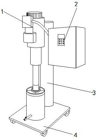
[0024] like Figure 1-Figure 4 shown:

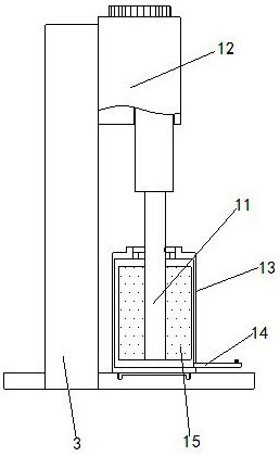
[0025] The present invention is a cosmetic liquid mixer, its structure includes a stirring mechanism 1, a control box 2, a fixed column 3, and a moving plate 4, the stirring mechanism 1 is installed on the side of the fixed column 3, and the control box 2 is embedded in the fixed column. 3 side, the lower end of the fixed column 3 is welded on the surface of the moving plate 4, the stirring mechanism 1 is located at the upper end of the moving plate 4, and the stirring mechanism 1 is provided with a rotating shaft 11, a motor 12, a stirring barrel 13, an outflow Pipe 14, agitator 15, the motor 12 is installed on the side of the fixed column 3, the rotating shaft 11 is embedded in the motor 12, the agitator 15 is located inside the mixing barrel 13, and the agitator 15 is fitted On the outside of the rotating shaft 11, the lower end of the mixing barrel 13 is mounted on the surface of the moving plate 4, the left end of the outflow pipe ...

Embodiment 2

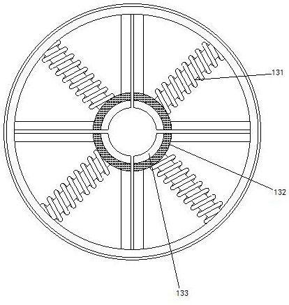
[0031] like Figure 5-Figure 7 shown:

[0032] The agitator 15 is provided with a fixed ring 151, a rotating ring 152, a sphere 153, a steel rod 154, and a drainage mechanism 155. The steel rod 154 is installed on the outer side of the fixed ring 151, and the rotating ring 152 is embedded. On the outer side of the steel rod 154 , the inner side of the drainage mechanism 155 is attached to the outer side of the fixing ring 151 , the fixing ring 151 is attached to the outer side of the lower end of the rotating shaft 11 , and the sphere 153 is embedded in the rotating ring 152 . Inside, there are two steel rods 154, which are symmetrically distributed on both sides of the drainage mechanism 155, and are in an irregular installation state, so that the cosmetic liquid is shunted through the steel rods 154 to achieve the effect of full mixing.

[0033] The fixing ring 151 is provided with a blocking mechanism w1 and a bending plate w2, the blocking mechanism w1 is installed in the...


PUM


Abstract

The invention discloses a cosmetic liquid stirrer. The cosmetic liquid stirrer comprises a stirring mechanism, a control box, a fixed column and a movable plate, the stirring mechanism is provided with a rotating shaft, a motor, a stirring barrel, an outflow pipe and a stirrer, the control box is controlled to enable the motor to rotate to drive the rotating shaft to rotate so that the stirrer rotates on the inner wall of the stirring barrel and sufficiently contacts with a cosmetic liquid, threaded strips are in threaded fit with the outer side of the rotating shaft, so that the tightness ofthe gap is higher, the problem that the cosmetic liquid splashes out of the gap is prevented, the beeswax solid precipitate enters an iron wire rod in a blocking mechanism under the action of rotatingforce, the dissolving speed is increased under the continuous impact force of a cosmetic liquid, and the cosmetic liquid flows out of a fixing ring and then enters a steel rod, so that the cosmetic liquid is shunted, the flowing direction is changed, the cosmetic liquid is prevented from being synchronous with the stirring direction, and the stirring degree of the cosmetic liquid is improved.

Description

technical field [0001] The invention relates to the field of cosmetic machinery, in particular to a cosmetic liquid mixer. Background technique [0002] In the production process of cosmetics, it is necessary to stir the raw materials of cosmetics. The current cosmetic mixers rely on the stirring shaft to stir, and the liquid stirring shaft of cosmetics has the function of stabilizing the rotation speed. However, when the cosmetic liquid is rotated and stirred, the high-speed rotation will form a swirling pattern, which will cause the cosmetic liquid to easily follow the direction of rotation, so that the cosmetic liquid moves synchronously along the edge of the mixing barrel and the stirring shaft, resulting in the same direction of force, reducing The degree of stirring of the cosmetic liquid causes the effect of stirring and mixing to be unsatisfactory, resulting in a low degree of dissolution of the beeswax solid sediment in the cosmetic liquid, and the cosmetic liquid w...

Claims


Application Information

Patent Timeline
Patent Type & Authority Applications(China)
IPC IPC(8): B01F7/18B01F1/00
CPCB01F21/10B01F27/90B01F2101/21
Inventor 翁红英
Owner 广州沐风信息科技有限公司
Why Eureka
Try Eureka