
State monitoring method and system of suspension control system and related device

A suspension control and state technology, used in transportation and packaging, electric traction, electric vehicles, etc., can solve problems such as large workload and time, poor performance, and cannot be found, achieve health monitoring, and avoid failure to run. Effect

Active Publication Date: 2020-09-18
NAT UNIV OF DEFENSE TECH
View PDF5 Cites 3 Cited by
  • Summary
  • Abstract
  • Description
  • Claims
  • Application Information

AI Technical Summary

Problems solved by technology

[0004] Most of the existing fault prediction and health management technologies only monitor and predict the state of the system, and do not take corresponding measures to prolong the remaining service life of the system in the process of system performance degradation
Secondly, the control strategy of extending the remaining service life of the system by changing the control parameters needs to repeatedly change the controller parameters and download the program to the control board, or even find better controller parameters, which will result in a lot of work and effort. time, which directly leads to poor monitoring and poor performance

Method used


Image

  • State monitoring method and system of suspension control system and related device
  • State monitoring method and system of suspension control system and related device
  • State monitoring method and system of suspension control system and related device

Examples


Embodiment Construction

[0048] In order to make the purposes, technical solutions and advantages of the embodiments of the present application clearer, the technical solutions in the embodiments of the present application will be clearly and completely described below in conjunction with the drawings in the embodiments of the present application. Obviously, the described embodiments It is a part of the embodiments of this application, not all of them. Based on the embodiments in this application, all other embodiments obtained by persons of ordinary skill in the art without making creative efforts belong to the scope of protection of this application.

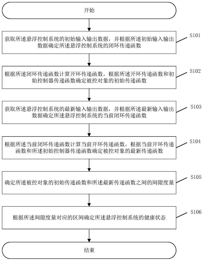
[0049] Please refer to figure 1 , figure 1 It is a flow chart of a state monitoring method for a suspension control system provided in an embodiment of the present application, and the method includes:

[0050] S101: Obtain initial input and output data of the suspension control system, and determine a closed-loop transfer function of the suspension...


PUM


Abstract

The invention provides a state monitoring method of a suspension control system. The state monitoring method comprises the steps of: obtaining input data and output data of the suspension control system; determining a corresponding model molecular denominator order and a closed-loop transfer function of the suspension control system according to the input data; calculating an open-loop transfer function according to the closed-loop transfer function; determining a transfer function of the controlled object according to the open-loop transfer function and the initial controller transfer function; determining a gap metric according to the transfer function of the controlled object and a first preset formula; and determining the health state of the suspension control system according to the interval corresponding to the gap measurement. According to the method, the gap between the controlled object transfer function and the controlled object transfer function of the initial system is measured as the health index of the system, so that health monitoring is realized, and the problems that a train cannot run, the economic loss is serious and the maintenance cost is high are avoided. Theinvention further provides a state monitoring system of the suspension control system, a computer readable storage medium and electronic equipment, which have the above beneficial effects.

Description

technical field [0001] The present application relates to the field of electronic equipment safety, in particular to a state monitoring method, system and related devices of a suspension control system. Background technique [0002] The levitation system is one of the core systems of the maglev train. If the suspension system breaks down, the train will not be able to run, and serious economic losses and maintenance costs will result. System failure is not that the system is completely inoperable, but that the performance of the system is not within the ideal range. [0003] In order to solve this problem, fault prediction and health management are required. At present, the vast majority of fault prediction and health management are abnormal detection, health monitoring, fault diagnosis, fault prediction and health management of the system, among which the health monitoring technology mainly adopts the deterministic index and robustness index in the performance index of th...

Claims


Application Information

Patent Timeline
IPC IPC(8): B60L13/06G06F17/15
CPCB60L13/06G06F17/15
Inventor 龙志强王平翟明达窦峰山
Owner NAT UNIV OF DEFENSE TECH
Learn More