Polystyrene vacuum automatic packaging molding machine

A polystyrene, automatic packaging technology, applied in vacuum/special atmosphere packaging, packaging, transportation packaging, etc., can solve the problems of long operation time and low efficiency, and achieve the effect of saving time and improving work efficiency

Active Publication Date: 2022-01-07
湖南天阁食品有限公司
View PDF10 Cites 0 Cited by
  • Summary
  • Abstract
  • Description
  • Claims
  • Application Information

AI Technical Summary

Problems solved by technology

[0004] The purpose of the present invention is to solve the problem that most of the existing vacuum packaging machines first carry out vacuum extraction in the vacuum, and then seal after reaching a predetermined vacuum degree, and after the sealing is completed, the vacuum packaging machine needs to be opened manually, and the polystyrene The packaging bag is taken out of the vacuum chamber, the operation time is long and the efficiency is low, and the proposed polystyrene vacuum automatic packaging molding machine

Method used


Image

  • Polystyrene vacuum automatic packaging molding machine
  • Polystyrene vacuum automatic packaging molding machine
  • Polystyrene vacuum automatic packaging molding machine

Examples


Embodiment 1

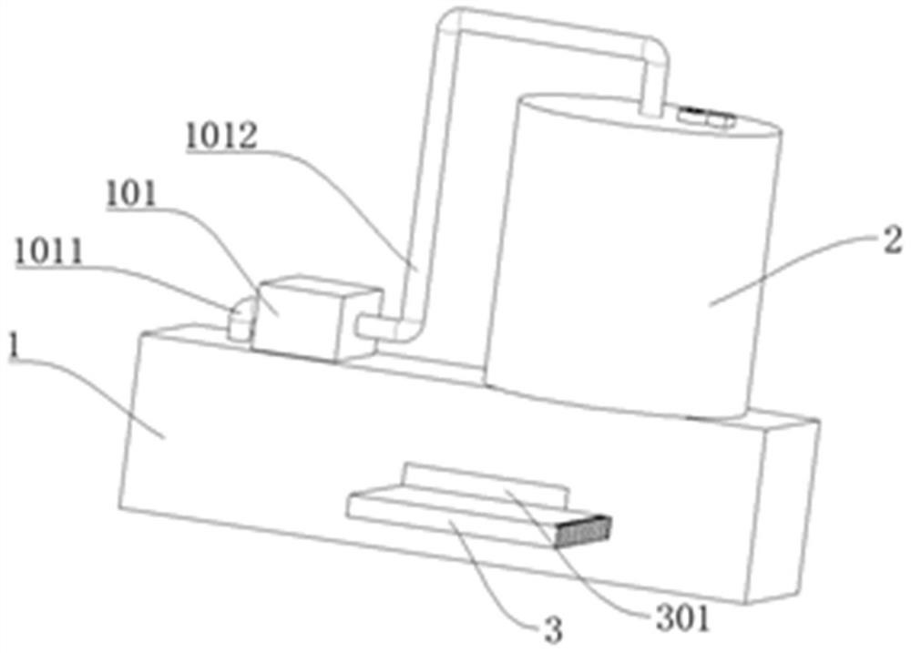
[0032] refer to Figure 1-7 , a polystyrene vacuum automatic packaging molding machine, comprising a box body 1, an air pump 101, and a heat press sealing machine 4011, the box body 1 is provided with a vacuum chamber 1001, the air pump 101 and the box body 1 are connected through a first connecting pipe 1011, and Including the gas cylinder 2, the gas cylinder 2 and the suction pump 101 are connected through the second connecting pipe 1012, the piston plate 4 is slidably connected in the gas cylinder 2, the lower end of the piston plate 4 is fixedly connected with the connecting plate 401, and the connecting plate 401 is slidably connected to the gas cylinder 2, the box body 1, the heat press sealing machine 4011 is connected to the bottom end of the connection plate 401, and the transmission and placement plate 3 is slidably connected to the box body 1, and the transmission and placement plate 3 is connected to the connection plate 401.

[0033] When the user is in use, by cl...

Embodiment 2

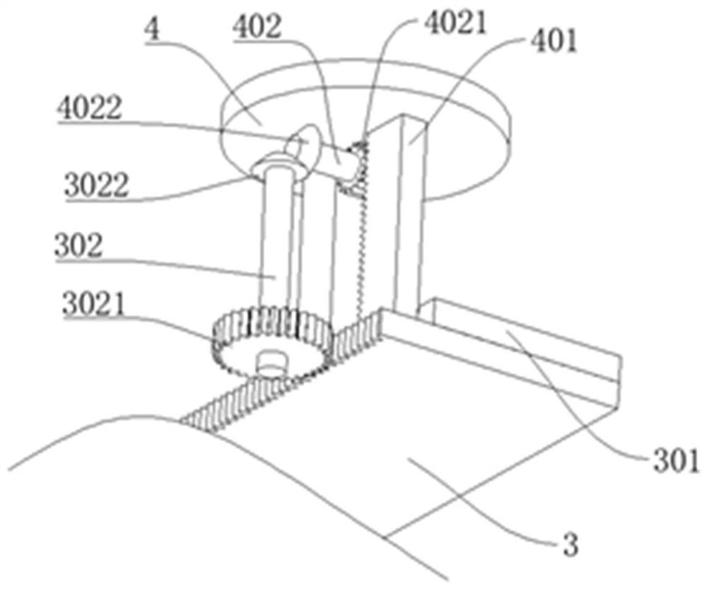
[0035] refer to Figure 1-7, which is basically the same as that of Embodiment 1, furthermore, the gas cylinder 2 is fixedly connected with a support plate 4033, the support plate 4033 is rotatably connected with a second rotating shaft 402, and the two ends of the second rotating shaft 402 are respectively connected with a driving gear 4021, a second rotating shaft Two helical gears 4022, the casing 1 is rotatably connected with a first rotating shaft 302, and the two ends of the first rotating shaft 302 are respectively connected with a first gear 3021 and a first helical gear 3022, and the first helical gear 3022 and the second helical gear 4022 are in phase meshing, the connecting plate 401 is provided with a tooth groove matching the driving gear 4021, and the transmission placement plate 3 is provided with a tooth groove matching the first gear 3021, the driving gear 4021 adopts a one-way gear, and the driving gear 4021 is clockwise When moving, the second rotating shaft...

Embodiment 3

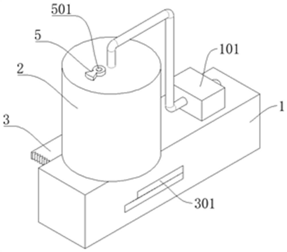
[0038] refer to Figure 1-7 , is basically the same as that of Embodiment 1, furthermore, the top of the gas cylinder 2 is provided with an exhaust port 2001, and the gas cylinder 2 is provided with an exhaust switch 5 that matches the exhaust port 2001, and the exhaust switch 5 is rotatably connected with a mobile Column 501, piston plate 4 is fixedly connected with telescopic rod 502, one end of moving column 501 is slidably connected in telescoping rod 502, threaded bar is provided on moving post 501, and threaded bar matching threaded bar is provided on exhaust switch 5 Groove, piston plate 4 upper ends are fixedly connected with spring 201, and the other end of spring 201 is fixedly connected with inflator 2 inner wall, and the junction of exhaust switch 5 and exhaust port 2001 is provided with rubber pad.

[0039] When the user is in use, when the piston plate 4 moves down, it will drive the telescopic rod 502 to move down, and the moving column 501 is slidably connected...


PUM


Abstract

The invention discloses a polystyrene vacuum automatic packaging forming machine, which belongs to the technical field of vacuum packaging. The polystyrene vacuum automatic packaging molding machine includes a box body, an air pump, and a heat-press sealing machine. The box body is provided with a vacuum chamber. The air cylinder and the air pump are connected through a second connecting pipe, a piston plate is slidably connected in the air cylinder, and a connecting plate is fixedly connected to the lower end of the piston plate, and the connecting plate is slidably connected to the air cylinder and the box body, and the heat-press sealing The machine is connected to the bottom end of the connection plate, and the transmission and placement plate is slidably connected in the box, and the transmission and placement plate is connected with the connection plate. This device can vacuum the polystyrene packaging bag while vacuuming the vacuum chamber. Sealing, and after the sealing is completed, the polystyrene packaging bag is automatically removed.

Description

technical field [0001] The invention relates to the technical field of vacuum packaging, in particular to a polystyrene vacuum automatic packaging molding machine. Background technique [0002] Polystyrene refers to a polymer synthesized by free radical addition polymerization of styrene monomer. It is a colorless and transparent thermoplastic. Therefore, polystyrene is often used as a material for packaging bags; in order to prevent the products in the packaging bag from Due to the influence of air, the product deteriorates and the quality is damaged. Vacuum packaging machines are often used to extract the air in the packaging bag, and the sealing process is completed after reaching the predetermined vacuum degree. [0003] Most of the existing vacuum packaging machines first vacuum the vacuum chamber, and then seal after reaching the predetermined vacuum degree, and after the sealing is completed, the vacuum packaging machine needs to be manually opened to take out the pol...

Claims


Application Information

Patent Timeline
Patent Type & Authority Patents(China)
IPC IPC(8): B65B31/02B65B51/14
CPCB65B31/024B65B51/146
Inventor 王顺锋刘姣
Owner 湖南天阁食品有限公司
Why Eureka
Try Eureka