Basement outer wall backfill system and method

A technology for basement exterior walls and sand water, applied in excavation, wine cellars, building components, etc., can solve the problems of low efficiency of basement exterior wall backfill construction, poor civilized construction image, time-consuming and laborious, etc., to avoid traffic congestion, civilized The construction image is good and the effect of preventing the loss of sand and gravel

Pending Publication Date: 2020-09-18
THE THIRD CONSTR OF CHINA CONSTR EIGHTH ENG BUREAU
View PDF0 Cites 0 Cited by
  • Summary
  • Abstract
  • Description
  • Claims
  • Application Information

AI Technical Summary

Problems solved by technology

Routinely, it is difficult to unload and transport the backfill to the outdoor wall of the basement for direct backfilling. Measures such as reinforcement of the roof, adjustment of the fence near the red line, adjustment of the power supply, and adjustment of the water are required, which is time-consuming and laborious, and the image of civilized construction is poor.
Therefore, the backfill construction efficiency of the basement exterior wall in the prior art is low

Method used


Image

  • Basement outer wall backfill system and method
  • Basement outer wall backfill system and method
  • Basement outer wall backfill system and method

Examples


Embodiment 1

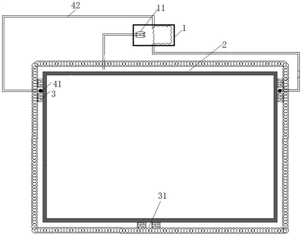
[0037] Embodiment 1: A kind of backfilling system of basement exterior wall, such as Figure 1-3 As shown, it includes a sand-water mixing tank 1 and a sand pump delivery pipe 11. The sand-water mixing tank 1 is used to collect the sand-water mixture to be filled, that is, the sand to be filled is mixed with water in the sand-water mixing tank 1 and stirred Evenly, the sand pump conveying pipe 11 pumps the sand-water mixture in the sand-water mixing tank 1 into the fertilizer tank 2 for backfill operation.

[0038] Among them, one end of the sand pump delivery pipe 11 is connected to the sand-water mixing tank 1, and the other end is connected to the fertilizer tank 2. It can be understood that the sand-water mixing tank 1 can be constructed according to the site conditions. The pump delivery pipe 11 is enough to pump the sand-water mixture in the sand-water mixing tank 1 into the fertilizer tank 2, which solves the problem that the backfill soil is difficult to transport and ...

Embodiment 2

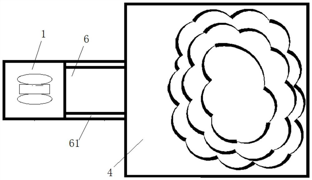
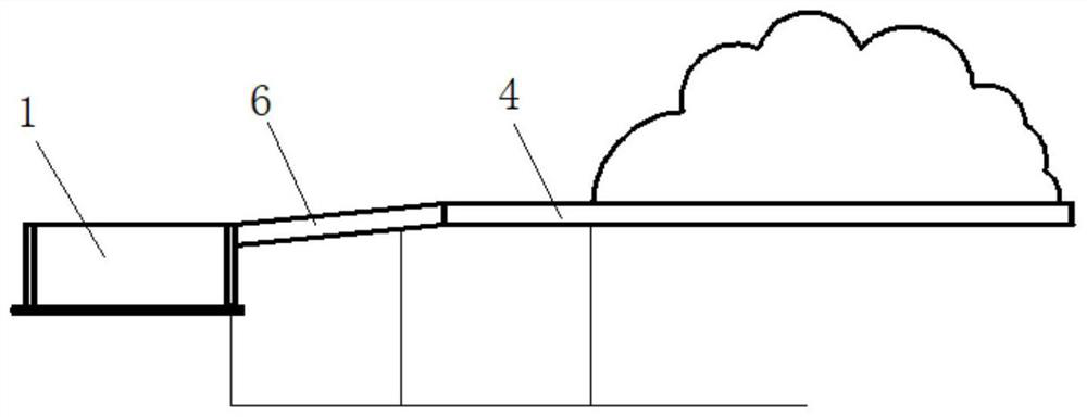
[0053] Embodiment 2: A basement outdoor wall backfill system, the difference from Embodiment 1 is that, as Figure 4 and 5 As shown, since the fertilizer tank 2 is filled with a mixture of sand and water, in which there is more useless water, in order to discharge excess water in time, a water filter is arranged in the fertilizer tank 2, and the water filter is connected with a drainage device.

[0054] Wherein, a plurality of water filtering devices can be provided, and the plurality of water filtering devices are evenly spaced in the fertilizer tank 2 . In practical application, a water filter device can be installed every 100~200m.

[0055] The water filtering device includes two sandbag walls 3 , and a water filtering space 31 is left between the sandbag walls 3 , one end of the drainage device communicates with the water filtering space 31 , and the other end communicates with the outside of the fertilizer tank 2 . In practical application, the distance between two sand...


PUM


Abstract

The invention discloses a basement outer wall backfill system and method, and relates to the technical field of construction. The system comprises a sand and water mixing pond and a sand pump conveying pipe, the sand and water mixing pond is used for collecting a sand and water mixture to be filled, one end of the sand pump conveying pipe communicates with the sand and water mixing pond, the otherend of the sand pump conveying pipe communicates into a flat groove, a water filter device is arranged in an excavated part, the water filter device communicates with a water draining device, sand and water can be mixed, the sand and water mixture can be formed, the sand pump conveying pipe is used for pumping the sand and water mixture to the excavated part, the problems that backfill is difficult to transport, load and unload, and the basement outer wall excavated part space is small and narrow can be solved, and the basement outer wall backfill construction efficiency is improved.

Description

technical field [0001] The invention relates to the technical field of construction, and more specifically, to a system and method for backfilling basement exterior walls. Background technique [0002] At present, the backfilling construction of the basement outer wall usually involves earth vehicles unloading and transporting the backfill soil to the vicinity of the basement outer wall, using manual excavators to carry out earthwork backfilling, and using road rollers, plate compactors and other machinery for compaction. With the development of the city, the land use is getting tighter, the depth of the foundation pit is getting deeper and deeper, and the distance between the outer wall of the basement and the red line is getting closer and closer. Conventionally, it is difficult to unload and transport the backfill soil to the outdoor wall of the basement for direct backfilling. It is necessary to take measures such as reinforcement of the roof, adjustment of the fence nea...

Claims


Application Information

Patent Timeline
Patent Type & Authority Applications(China)
IPC IPC(8): E02D15/00E02D17/12E04B1/00
CPCE02D15/00E02D17/12E04B1/0007
Inventor 殷帅杰李书信全有维刘亚松陆超豪张帆
Owner THE THIRD CONSTR OF CHINA CONSTR EIGHTH ENG BUREAU
Why Eureka
Try Eureka