
Functional modular photoelectric autocollimator and optical path debugging method thereof

A technology of photoelectric autocollimator and functional module, which is applied in the field of optics and can solve the problems of low debugging efficiency of photoelectric autocollimator

Pending Publication Date: 2020-09-18
XI'AN INST OF OPTICS & FINE MECHANICS - CHINESE ACAD OF SCI
View PDF0 Cites 0 Cited by
  • Summary
  • Abstract
  • Description
  • Claims
  • Application Information

AI Technical Summary

Problems solved by technology

[0006] In order to solve the technical problem of low debugging efficiency of photoelectric autocollimators with commonly used structures at present, the present invention proposes a functional modular photoelectric autocollimator and its optical path debugging method

Method used


Image

  • Functional modular photoelectric autocollimator and optical path debugging method thereof
  • Functional modular photoelectric autocollimator and optical path debugging method thereof
  • Functional modular photoelectric autocollimator and optical path debugging method thereof

Examples


Embodiment Construction

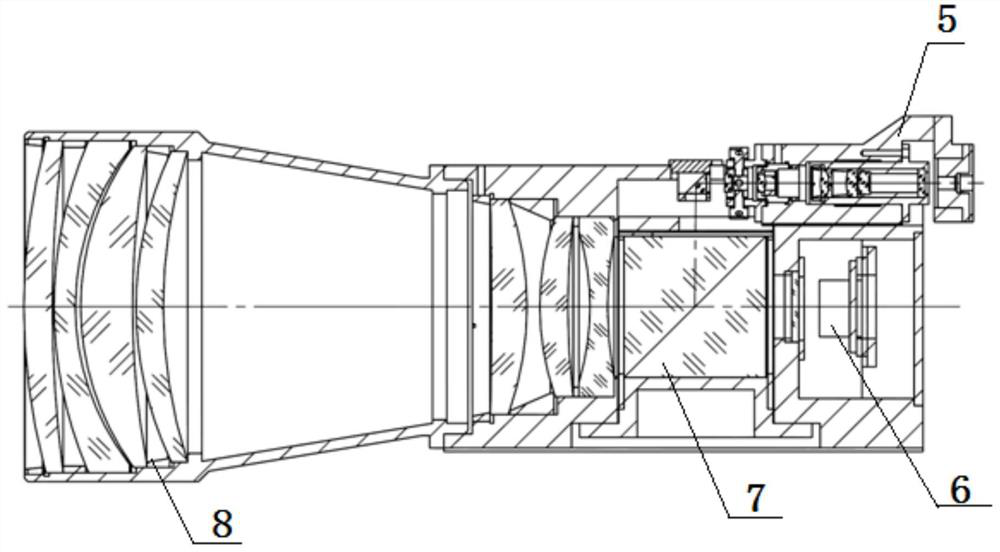
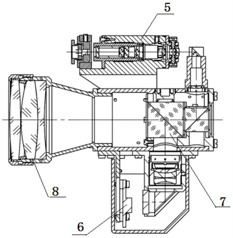
[0029] The improvement of the present invention lies in the modular design of the photoelectric autocollimator according to the debugging requirements and debugging functions, and the photoelectric autocollimator is divided into four independently assembled functional modules.

[0030] Such as Figure 4 As shown, the four functional modules are an objective lens module 101 , a dichroic prism module 104 , a light source slit module 105 and a CCD module 106 . The beam-splitting prism module 104 is arranged on the output optical path of the objective lens module 101 and the two are on the same optical axis, the light source slit module 105 is arranged on the transmission optical path of the beam-splitting prism module 104 and the two are on the same optical axis, and the CCD module 106 is arranged on the beam-splitting prism module 104 on the reflected light path. Both the objective lens module 101 and the dichroic prism module 104 are arranged on the base 103, and are closely m...


PUM


Abstract

In order to solve the technical problem of low debugging efficiency of a photoelectric autocollimator with a common structure at present, the invention provides a functional modular photoelectric autocollimator and an optical path debugging method thereof. According to the invention, modular design is carried out on the photoelectric autocollimator according to debugging requirements and functionsof a slit image; decoupling of three debugging links of clear slit images, vertical debugging links and centering debugging links in optical path debugging of the photoelectric autocollimator is achieved, all the adjusting links do not interfere with one another, the adjusting process is simple and convenient, the optical path debugging time of a single photoelectric autocollimator is shortened to 5 min, and the debugging efficiency is improved by more than 10 times.

Description

technical field [0001] The invention relates to the field of optical technology, in particular to a functional modular photoelectric autocollimator and an optical path debugging method thereof. Background technique [0002] Photoelectric autocollimator is an optical instrument that uses the principle of self-collimation of light to measure flatness and small inclination. At present, a variety of optical instruments that measure and transmit small angles are integrated with photoelectric autocollimators. Two common photoelectric autocollimator structures are as follows: figure 1 , 2 As shown, the structure of the light source slit assembly 5 of these two photoelectric autocollimators is similar, as Figure 5 As shown, the light source slit assembly 5 is fastened by four adjustment screws up, down, left, and right. [0003] The adjustment method of the slit image is as follows: [0004] Moving back and forth to adjust the light source slit assembly 5 can realize the adjust...

Claims


Application Information

Patent Timeline
Patent Type & Authority Applications(China)
IPC IPC(8): G01B11/27G02B27/30
CPCG01B11/272G02B27/30
Inventor 赵小东白建明杨东来于芳苏
Owner XI'AN INST OF OPTICS & FINE MECHANICS - CHINESE ACAD OF SCI
Features
  • Generate Ideas
  • Intellectual Property
  • Life Sciences
  • Materials
  • Tech Scout
  • Unparalleled Data Quality
  • Higher Quality Content
  • 60% Fewer Hallucinations
Learn More