Amplifying lens structure

A lens and lens barrel technology, applied in the field of magnifying lens structure, can solve problems such as difficulty in ensuring stability

Pending Publication Date: 2020-09-18
中山北方晶华精密光学有限公司
View PDF0 Cites 0 Cited by
  • Summary
  • Abstract
  • Description
  • Claims
  • Application Information

AI Technical Summary

Problems solved by technology

However, it is difficult to ensure the stability of a group with a large number of lenses using a single pressure ring. Therefore, how to overcome the above-mentioned defects has become an important issue to be solved urgently by those skilled in the art.

Method used


Image

  • Amplifying lens structure
  • Amplifying lens structure
  • Amplifying lens structure

Examples


Embodiment Construction

[0020] The features of the present invention and other relevant features are described in further detail below through the embodiments, so as to facilitate the understanding of those skilled in the art:

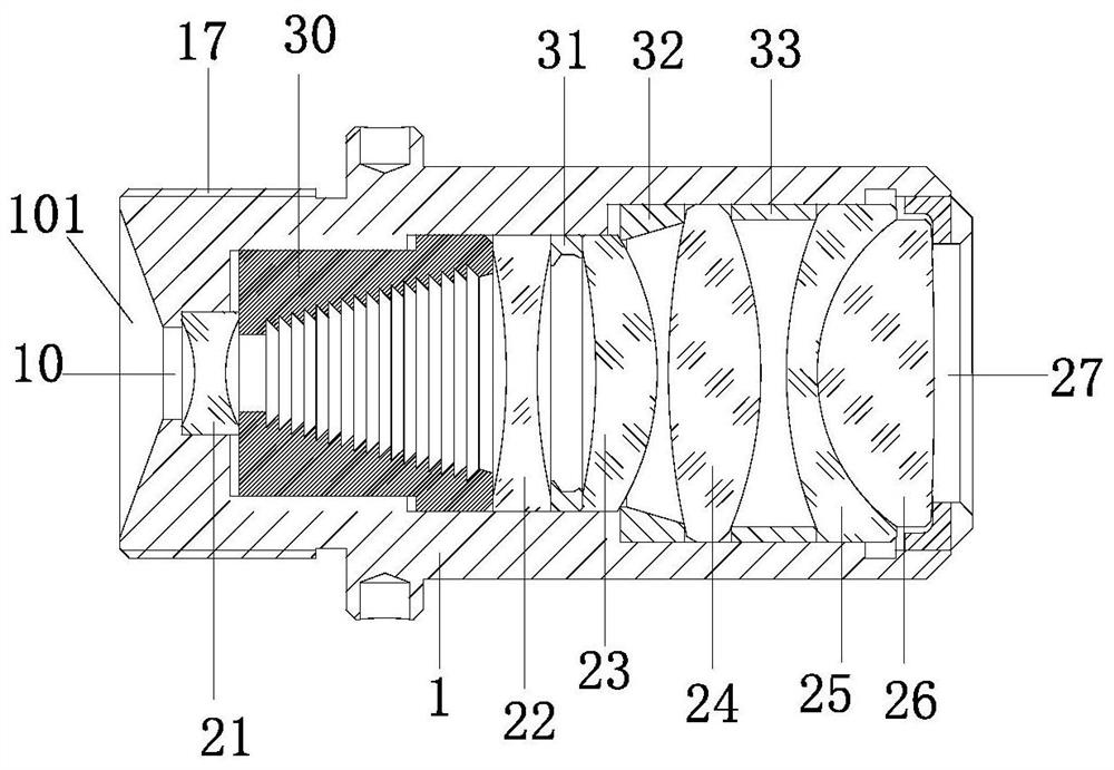
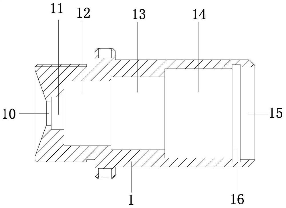
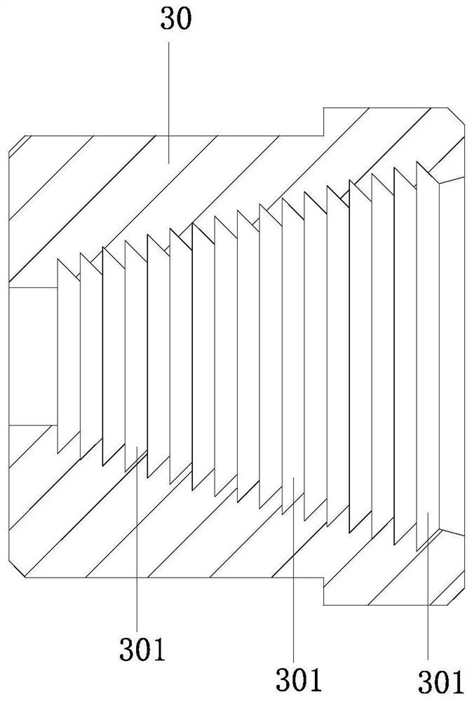
[0021] like Figure 1 to Figure 4 As shown, a magnifying lens structure includes an outer lens barrel 1, and the outer lens barrel 1 is sequentially provided with a circular limiting channel 10 at the image side end arranged from small to large inner diameters from the image side to the object side. A circular channel 11, a second circular channel 12, a third circular channel 13, a fourth circular channel 14, and a circular opening channel 15 at the object side end. The first biconcave lens 21, the inner lens barrel 30, the second biconcave lens 22, the first spacer 31, the third meniscus lens 23, the second spacer 32, the fourth biconvex lens 24, the third Spacer 33, the fifth meniscus lens 25, the sixth biconvex lens 26, each lens has object side and image side, the image ...


PUM


Abstract

The invention discloses an amplifying lens structure. An image side end circular limiting channel, a first circular channel, a second circular channel, a third circular channel, a fourth circular channel and an object side end circular opening channel are sequentially arranged in an outer lens barrel from the image side to the object side, and the inner diameters of the channels are arranged fromsmall to large. A first biconcave lens, an inner lens barrel, a second biconcave lens, a first space ring, a third meniscus lens, a second space ring, a fourth biconvex lens, a third space ring, a fifth meniscus lens and a sixth biconvex lens which are sequentially close to one another in the direction from the image side to the object side are mounted in the outer lens barrel; and the inner sidewall of the circular opening channel at the object side end is in threaded connection with a compression nut used for pressing the sixth biconvex lens, so that the components from the first biconcavelens to the sixth biconvex lens are ensured to be close to each other in sequence so as to keep the distance between the lenses, and the lens is stable and practical.

Description

technical field [0001] The invention relates to a magnifying lens structure. Background technique [0002] With the widespread application of lenses in monitoring, industrial inspection, intelligent transportation, scanning and copying equipment, and photographic cameras, the demand for lenses is getting higher and higher. It is required that the imaging of the lens should be clear, and the quality of the lens with high requirements will definitely be used more. Lenses for optical imaging. However, it is difficult to ensure the stability of a group with a large number of lenses using a single pressure ring. Therefore, how to overcome the above-mentioned defects has become an important issue to be solved urgently by those skilled in the art. Contents of the invention [0003] The invention overcomes the disadvantages of the above-mentioned technologies and provides a magnifying lens structure. [0004] To achieve the above object, the present invention adopts the followin...

Claims


Application Information

Patent Timeline
Patent Type & Authority Applications(China)
IPC IPC(8): G02B7/02
CPCG02B7/022
Inventor 袁志峰秦朝锋汤华锡胡书贤石妹吴志坚阳术刚
Owner 中山北方晶华精密光学有限公司
Why Eureka
Try Eureka