Modeling method of laser arc heat source model based on groove compression coefficient

A laser arc heat source and compressibility technology, applied in CAD numerical modeling, special data processing applications, design optimization/simulation, etc., can solve the problem of low accuracy of heat source model, and achieve the effect of solving the problem of width

Active Publication Date: 2020-09-18
HOHAI UNIV CHANGZHOU
View PDF1 Cites 4 Cited by
  • Summary
  • Abstract
  • Description
  • Claims
  • Application Information

AI Technical Summary

Problems solved by technology

[0005] In order to solve the deficiencies in the prior art, the present invention provides a modeling method of the laser arc heat source model based on the groove compression coefficient, which solves the problem of low precision of the laser arc hybrid welding heat source model for medium and thick plates

Method used


Image

  • Modeling method of laser arc heat source model based on groove compression coefficient
  • Modeling method of laser arc heat source model based on groove compression coefficient
  • Modeling method of laser arc heat source model based on groove compression coefficient

Examples


specific Embodiment example 1

[0064] Cut the alloy steel plate of 150mm×80mm×18.4mm, make a 30° V-shaped groove, and perform three-pass composite heat source multi-pass welding. The sample size is as follows: figure 2 shown. After cutting and surface treatment of X80 high-strength pipeline steel, debris and oil will exist on its surface. Therefore, before welding, sand the sample with sandpaper, then clean the sample with acetone, and finally wipe it with alcohol. The process parameters shown in Table 1 are used for welding.

[0065] Table 1 The welding process parameters used in Example 1

[0066]

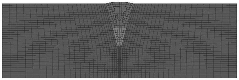
[0067] In order to ensure better calculation accuracy and less calculation amount, different division methods and grid density were carried out in different regions according to the model when dividing the grid. The solid70 hexahedral thermal analysis unit was used in the weld and its surrounding areas and For fine mesh division, the solid70 hexahedral thermal element is used for coarse mesh division in...

specific Embodiment example 2

[0072] Cut the alloy steel plate of 150mm×80mm×18.4mm, make a 30° V-shaped groove, and perform three-pass composite heat source multi-pass welding. The sample size is as follows: figure 2 shown. After cutting and surface treatment of X80 high-strength pipeline steel, debris and oil will exist on its surface. Therefore, before welding, sand the sample with sandpaper, then clean the sample with acetone, and finally wipe it with alcohol. The process parameters shown in Table 2 are used for welding.

[0073] The welding process parameters used in the second example of Table 2

[0074]

[0075] In order to ensure better calculation accuracy and less calculation amount, different division methods and grid density were carried out in different regions according to the model when dividing the grid. The solid70 hexahedral thermal analysis unit was used in the weld and its surrounding areas and For fine mesh division, the solid70 hexahedral thermal element is used for coarse mesh...


PUM


Abstract

The invention discloses a modeling method for a laser arc heat source model based on a groove compression coefficient, and the method comprises the steps: 1, building a composite heat source model composed of three heat sources, and adding a groove compression function on the basis of a double-ellipsoid heat source model and a cylindrical heat source model; 2, according to the shape of the fusionline of a welding joint, repeatedly checking the welding heat source parameters by applying an acceleration step method to obtain a correspondingly simulated molten pool shape; and 3, serving the goodness of fit between the simulated molten pool shape and the actual molten pool shape as a standard for determining whether the groove compression function is accurate or not, and obtaining an optimalnumerical simulation heat source model. The problem of depth is solved by adding a cylindrical heat source on the basis of two original heat sources, the method can be better suitable for medium plates, and the groove compression function is added on the basis of the original double-ellipsoid and cylindrical heat sources, so that the problem of width is solved, and the fusion depth is closer to anactual weld joint to a certain extent.

Description

technical field [0001] The invention relates to a modeling method of a laser arc heat source model based on groove compression coefficient, and belongs to the technical field of welding numerical simulation heat source models. Background technique [0002] Laser arc hybrid welding has the characteristics of large penetration depth of laser welding and low assembly accuracy requirements of ordinary arc welding. Compared with single laser welding and single arc welding, it has great advantages. , Automobile ships and transportation tracks and other industries have a wide range of applications. The recognized method for the research of laser arc hybrid welding is to study the laser arc hybrid welding process through numerical simulation technology, so as to play a guiding role in engineering practice. [0003] At present, most of the studies on the heat source model of hybrid welding use the combination of two heat sources. In this case, the composite heat source model can be ...

Claims


Application Information

Patent Timeline
Patent Type & Authority Applications(China)
IPC IPC(8): G06F30/23G06F111/10
CPCG06F30/23G06F2111/10
Inventor 严春妍张浩朱子江易思张可召侯佳兵
Owner HOHAI UNIV CHANGZHOU
Why Eureka
Try Eureka