
Array substrate and display panel

An array substrate and transistor technology, applied to static indicators, identification devices, instruments, etc., can solve the problems of increased time, unfavorable high refresh rate of display panels, increased parasitic capacitance of data signal lines, etc., to reduce the risk of leakage, Guaranteed display uniformity and reduced latency

Active Publication Date: 2022-03-18
KUNSHAN GO VISIONOX OPTO ELECTRONICS CO LTD
View PDF9 Cites 0 Cited by
  • Summary
  • Abstract
  • Description
  • Claims
  • Application Information

AI Technical Summary

Problems solved by technology

However, the above process tends to increase the parasitic capacitance on the data signal line, which in turn leads to an increase in the time required to write the data voltage during the data writing phase, which is not conducive to the high refresh rate of the display panel.

Method used


Image

  • Array substrate and display panel
  • Array substrate and display panel
  • Array substrate and display panel

Examples


Embodiment Construction

[0026] The present invention will be further described in detail below in conjunction with the accompanying drawings and embodiments. It should be understood that the specific embodiments described here are only used to explain the present invention, but not to limit the present invention. In addition, it should be noted that, for the convenience of description, only some structures related to the present invention are shown in the drawings but not all structures.

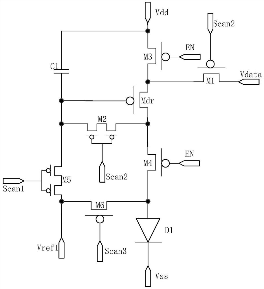
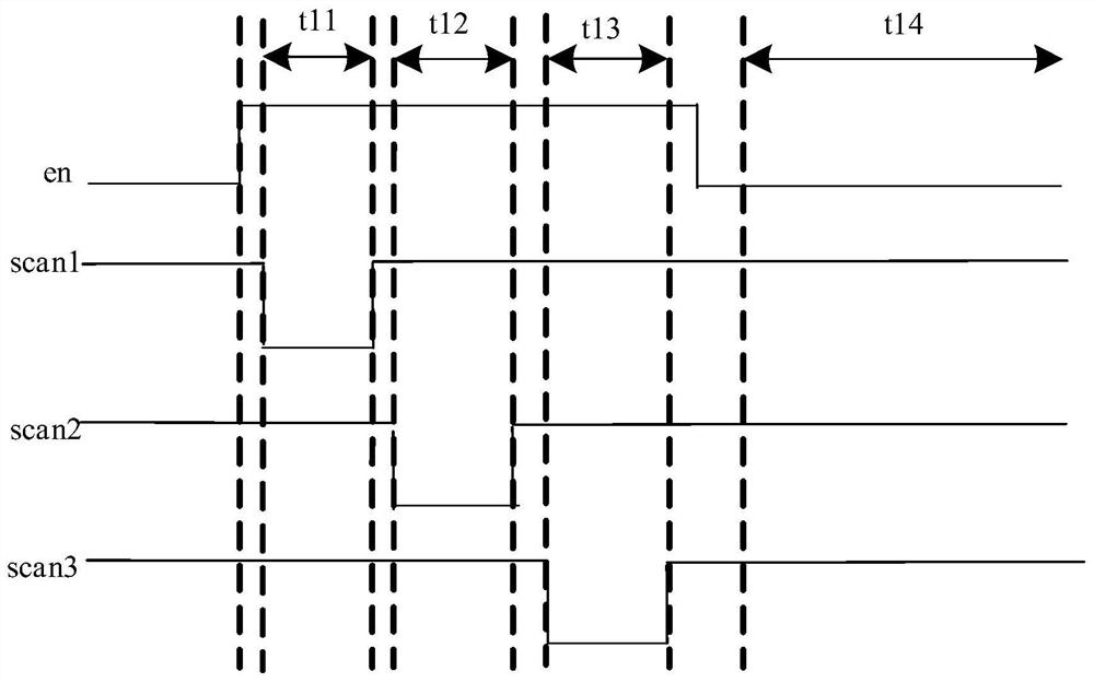
[0027] figure 1 It is a structural schematic diagram of an existing pixel driving circuit. Such as figure 1 As shown, the pixel driving circuit includes a driving transistor Mdr, a first transistor M1, a second transistor M2, a third transistor M3, a fourth transistor M4, a fifth transistor M5, a sixth transistor M6, a storage capacitor C1 and a light emitting device D1. The driving transistor Mdr, the first transistor M1 , the second transistor M2 , the third transistor M3 , the fourth transistor M4 , the fifth...


PUM


Abstract

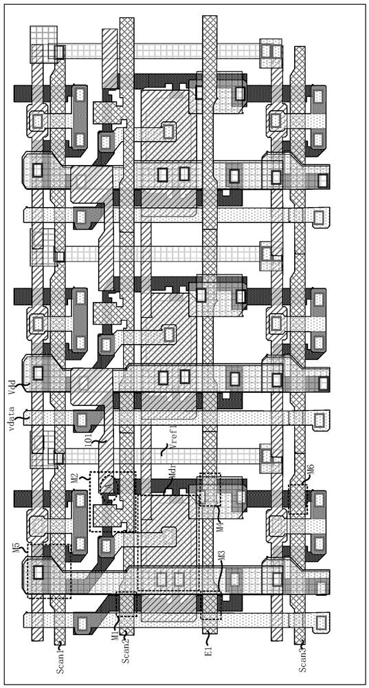
The invention discloses an array substrate and a display panel. The array substrate includes a substrate and a driving circuit layer on the substrate. A pixel driving circuit is arranged in the driving circuit layer, and each pixel driving circuit includes a threshold compensation transistor; the threshold compensation transistor includes a first channel region, a second channel region and the middle active region, the middle active region is set between the first channel region and the second channel region; the first voltage line and the data signal line are arranged in the driving circuit layer; the first voltage line and the middle active The vertical projections of the regions on the substrate at least partially overlap, and the vertical projections of the data signal lines and the first voltage lines on the substrate do not overlap. Not only can the variation of the gate potential of the driving transistor be reduced, but also the display uniformity of the display panel formed by the array substrate can be improved. At the same time, the delay generated when writing the data signal on the data signal line can be reduced, which is beneficial to reducing the time requirement for data writing, thereby facilitating the realization of a high refresh rate of the display panel.

Description

technical field [0001] Embodiments of the present invention relate to the field of display technologies, and in particular, to an array substrate and a display panel. Background technique [0002] The display panel can drive the light-emitting device to emit light through the pixel driving circuit to realize display. During the operation of the pixel driving circuit, the parasitic capacitance formed between the power signal line and the intermediate node of the threshold compensation transistor can be increased to ensure that the gate potential of the driving transistor remains unchanged after charging, thereby improving the display uniformity of the display panel. However, the above process tends to increase the parasitic capacitance on the data signal line, which further increases the time required for writing the data voltage during the data writing phase, which is not conducive to the high refresh rate of the display panel. Contents of the invention [0003] The inven...

Claims


Application Information

Patent Timeline
Patent Type & Authority Patents(China)
IPC IPC(8): G09F9/30G09F9/33H01L27/15H01L27/32G09G3/30G09G3/3225
CPCG09F9/30G09F9/33H01L27/156G09G3/30G09G3/3225H10K59/179
Inventor 赵虹姚远贾溪洋朱正勇
Owner KUNSHAN GO VISIONOX OPTO ELECTRONICS CO LTD
Learn More