

Multi-channel gyromagnetic filter magnetic circuit
A filter, multi-channel technology, applied in the direction of transformer/inductor core, circuit, transformer/inductor components, etc., can solve the problems of small current bearing capacity, small compensation coil frequency tuning and compensation range, and poor magnetic field uniformity. , to achieve the effect of improving the frequency compensation capability, increasing the compensation frequency modulation range, and reducing the control accuracy
- Summary
- Abstract
- Description
- Claims
- Application Information
AI Technical Summary
Problems solved by technology
Method used
Image

Examples
Embodiment 1
[0038] Example 1: X-Ku band rectangular magnetic pole four-channel integrated magnetic circuit
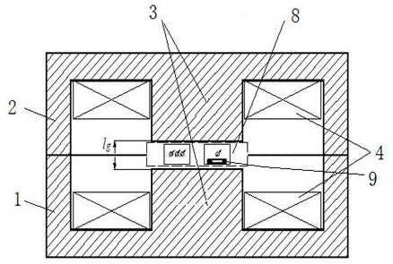
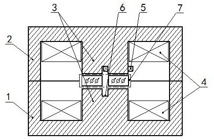
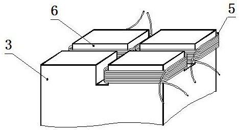
[0039] see figure 2 with 3 , X-Ku band rectangular magnetic pole four-channel integrated magnetic circuit: including lower magnetic circuit 1, upper magnetic circuit 2, magnetic pole column 3 of upper and lower magnetic circuits, main coil 4, compensation coil 5, coil installation slot 6 and multi-channel resonance circuit 7. The coil installation groove 6 is located at the end faces of the magnetic pole posts 3 of the upper and lower magnetic circuits and is vertical to the end faces. The end faces of the magnetic pole posts 3 of the upper and lower magnetic circuits are respectively divided into four parts, and the compensation coil 5 is set in the coil installation groove 6. The number of compensation coils 5 is 3. In the present embodiment, the 3 compensation coils 5 are respectively drawn out and then connected to respective current exciters, so that independent frequency co...
Embodiment 2
[0043] Embodiment 2: S-C band cylindrical magnetic pole four-channel integrated magnetic circuit
[0044] see figure 2 , Figure 4 , S-C band rectangular magnetic pole four-channel integrated magnetic circuit: including a lower magnetic circuit 1, an upper magnetic circuit 2, a magnetic pole 3 of the upper and lower magnetic circuits, a main coil 4, a compensation coil 5, a coil installation slot 6 and a multi-channel resonance circuit 7; The coil mounting groove 6 is located at the end face of the magnetic pole post 3 of the upper and lower magnetic circuit and is vertical to the end face, and the end face of the magnetic pole post 3 of the upper and lower magnetic circuit is divided into four parts respectively, and the compensation coil 5 is set in the coil mounting groove 6 to compensate The number of coils 5 is 4. In this embodiment, the 4 compensation coils 5 are respectively drawn out and connected to respective current actuators;
[0045] The four-way resonant circu...
Embodiment 3
[0046] Embodiment 3: S-C band rectangular magnetic pole column two-channel different-frequency tracking magnetic circuit
[0047] see figure 2 , Figure 5 , S-C band rectangular magnetic pole two-channel different-frequency tracking magnetic circuit: including lower magnetic circuit 1, upper magnetic circuit 2, magnetic pole column 3 of the upper and lower magnetic circuit, main coil 4, compensation coil 5, coil installation slot 6 and two resonant circuits 7. The coil installation groove 6 is located at the end faces of the magnetic pole posts 3 of the upper and lower magnetic circuits and is vertical to the end faces, and the end faces of the magnetic pole posts 3 of the upper and lower magnetic circuits are respectively divided into two parts, and the compensation coil 5 is set in the coil installation groove 6, The number of compensation coils 5 is two, which are respectively located in the coil installation grooves of the same partition of the upper and lower magnetic p...
PUM
 Abstract
Description
Claims
Application Information