Brush holder capable of monitoring temperature
A technology for monitoring temperature and brush holder, which is applied in the field of brush holders capable of monitoring temperature. It can solve problems such as heat generation, no guarantee of stable use of brush holders, and inability to monitor carbon brush temperature. It achieves simple structure, accurate and reliable temperature measurement, and small intervals. Effect
- Summary
- Abstract
- Description
- Claims
- Application Information
AI Technical Summary
Problems solved by technology
Method used
Image

Examples
Embodiment 1
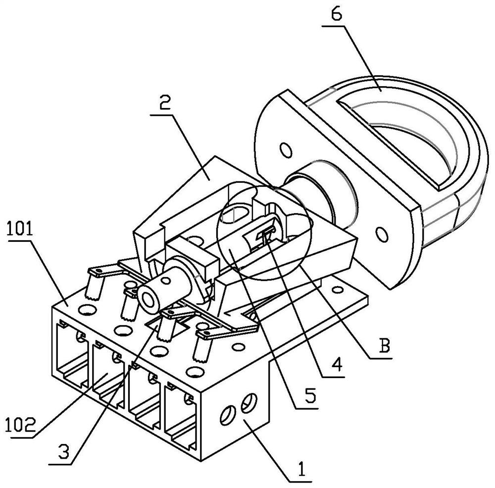
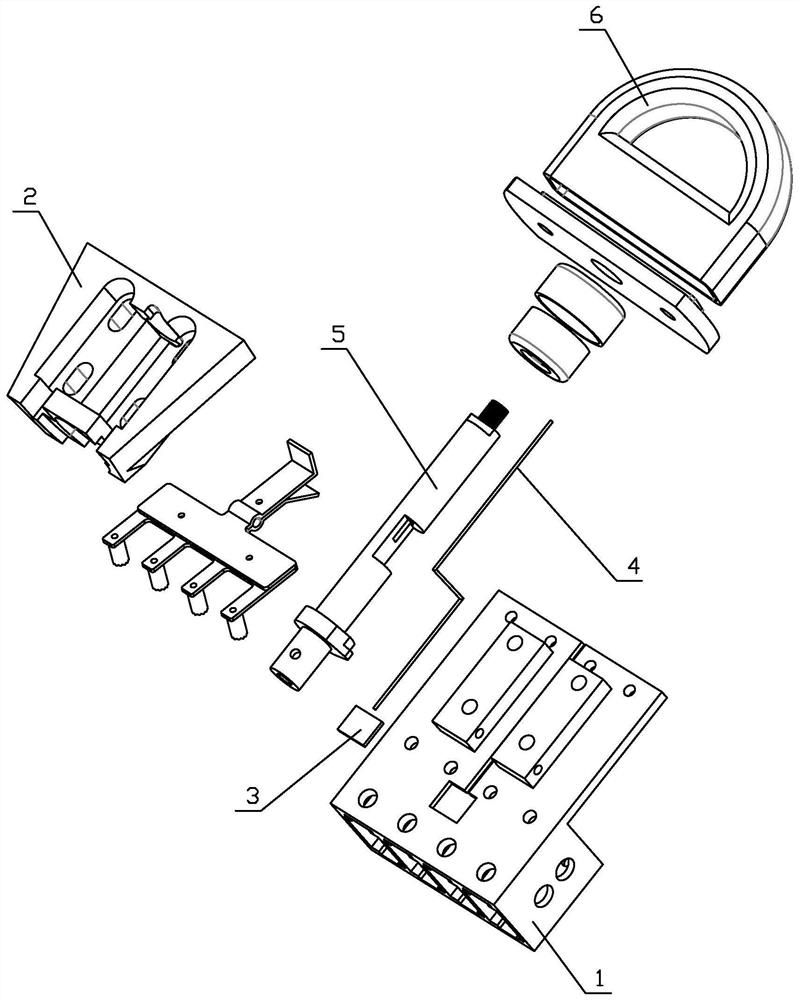
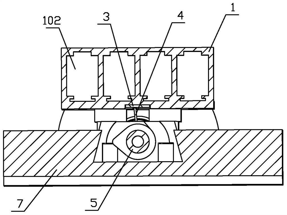
[0034] Such as figure 1 , figure 2 As shown, a brush holder capable of monitoring temperature includes a brush box 1. The brush box 1 includes a mounting surface 101 on which a mounting head 2 is fixed. The mounting head 2 is used to install the brush box 1 and also includes a temperature monitoring chip. 3. The temperature monitoring chip 3 is arranged on the mounting surface 101 , the brush box 1 is provided with a carbon brush chamber 102 , and the temperature monitoring chip 3 is arranged outside the chamber wall of the carbon brush chamber 102 .
[0035] In this embodiment, the mounting head 2 is provided with a horizontal tapered dovetail boss, and the base 7 is provided with a horizontal tapered dovetail groove.
[0036] In order to control the temperature of the carbon brushes, an air supply device is installed near the brush holder to dissipate heat for the carbon brushes through the rapid flow of air. Due to the fast air flow near the brush holder, the heat of the...
Embodiment 2
[0042] Such as Figure 9-12 As shown, the difference from Embodiment 1 is that this embodiment includes a connection block 9 which is fixedly connected to the brush box 1 , and an antenna 8 is fixed on the connection block 9 . The connecting block 9 is fixed on the side of the brush box and is made of copper. The mounting surface 101 is provided with a chip groove 903 and a first wire hole 901, the temperature monitoring chip 3 is arranged in the chip groove 903, the connecting block 9 is provided with a second wire hole 902 connected with the first wire hole 901, and the chip wire 4 Connect to the antenna 8 through the first wire hole 901 and the second wire hole 902 .
[0043] In this embodiment, a linear antenna is used, which is widely used and low in cost. The chip wires 4 are arranged in the first wire hole and the second wire hole, so that they are not easily damaged by external force.
PUM
 Abstract
Description
Claims
Application Information
 - R&D Engineer
- R&D Manager
- IP Professional
- Industry Leading Data Capabilities
- Powerful AI technology
- Patent DNA Extraction
Browse by: Latest US Patents, China's latest patents, Technical Efficacy Thesaurus, Application Domain, Technology Topic.
© 2024 PatSnap. All rights reserved.Legal|Privacy policy|Modern Slavery Act Transparency Statement|Sitemap