Magnetic stirrer for drug analysis

A technology of magnetic stirring and magnetic stirring bar, which is applied in the field of magnetic stirring devices for pharmaceutical analysis, which can solve the problems of inconvenient stirring, offset of stirring water column, unfavorable uniform stirring of drug solution, etc., and achieve the effect of convenient stirring and reducing shaking

Active Publication Date: 2022-03-08
新乡医学院三全学院
View PDF24 Cites 0 Cited by
  • Summary
  • Abstract
  • Description
  • Claims
  • Application Information

AI Technical Summary

Problems solved by technology

[0003] There is a heated magnetic stirrer on the market, which uses water bath heating to heat the stirred beaker, and at the same time, under the magnetic force of the magnetic stirrer, the stirring bar placed inside the beaker can be used to stir the solution inside the beaker , but when the existing magnetic stirrer is stirring, the stirring bar placed inside the beaker is under the action of the magnetic field formed at the bottom of the stirrer, the stirring bar is adsorbed and rotated, and a stirring water column is formed inside the beaker, and the stirring water column formed by the stirring bar is in the beaker At the center vertical line, the stirring water column drives other drug solutions inside the beaker to stir, and the stirring water column formed by the stirrer exists alone in the center of the beaker, which is not conducive to uniform stirring of the drug solution deviated from the center vertical line of the beaker. Water bath heating type, the water vapor with higher temperature generated makes the beaker placed inside the water bath shake, so that the stirring water column generated by the stirring bar is shifted, which is not convenient for the drug solution in the beaker to be stirred under the stirring water column formed by the stirring bar. To this end, we propose a magnetic stirring device for pharmaceutical analysis

Method used


Image

  • Magnetic stirrer for drug analysis
  • Magnetic stirrer for drug analysis
  • Magnetic stirrer for drug analysis

Examples


Embodiment Construction

[0026] The following will clearly and completely describe the technical solutions in the embodiments of the present invention with reference to the accompanying drawings in the embodiments of the present invention. Obviously, the described embodiments are only some, not all, embodiments of the present invention. Based on the embodiments of the present invention, all other embodiments obtained by persons of ordinary skill in the art without making creative efforts belong to the protection scope of the present invention.

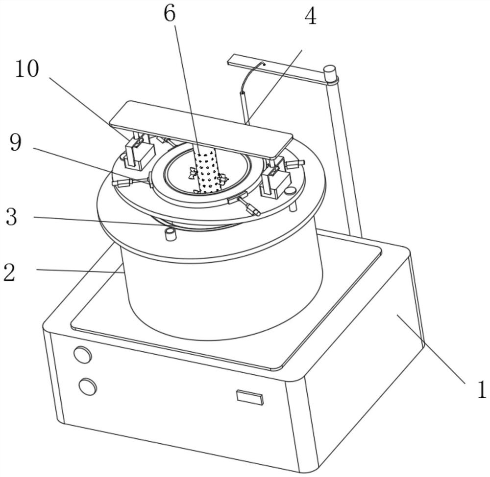
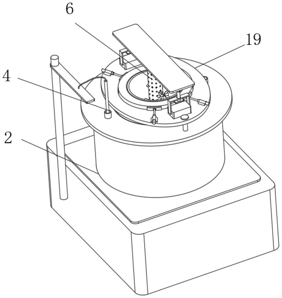
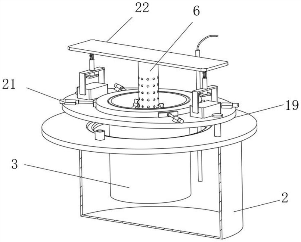
[0027] see Figure 1-10 , the present invention provides a technical solution: a magnetic stirring device for drug analysis. In this solution, when the existing magnetic stirrer 1 stirs the drug solution, the magnetic stirrer 11 forms a pair of stirring water columns located at the center of the beaker 3. The drug solution is stirred, which is unfavorable for stirring the drug solution inside the beaker 3 in multiple places. The design in this program includes...


PUM


Abstract

The invention discloses a magnetic stirring device for drug analysis, which includes a magnetic stirrer, a stirring shell is placed inside the beaker, and a stirring drum is connected to the top of the stirring shell, and a liquid leakage hole is provided on the outside of the stirring shell and the stirring drum. The inside of the stirring shell is provided with a multi-point stirring member for stirring the drug solution in the beaker at multiple places, the top of the beaker is connected with a clamping member for clamping the beaker, and the clamping member is connected with the top of the water bath, and the top of the stirring drum is connected There is a lifting member for lifting the stirring drum. When the magnetic stirrer is used to stir the drug solution in the present invention, the drug is placed inside the beaker, and the multi-point stirring member is placed inside the stirring shell at the same time. Under the action of stirring, the multi-point stirring member stirs inside the stirring shell, which facilitates the multi-point stirring of the solution inside the beaker. At the same time, the top of the beaker is clamped by the set clamping member to reduce the shaking of the beaker when the water bath is heated.

Description

technical field [0001] The invention relates to the technical field of stirring devices, in particular to a magnetic stirring device for drug analysis. Background technique [0002] Magnetic stirrer is a laboratory instrument used for liquid mixing. It is mainly used for stirring or simultaneously heating and stirring low-viscosity liquid or solid-liquid mixture. The magnetic field pushes the magnetic stirring bar placed in the container to run in a circle, so as to achieve the purpose of stirring the liquid. With the heating temperature control system, it can heat and control the sample temperature according to the specific experimental requirements, maintain the temperature conditions required by the experimental conditions, and ensure The liquid mixing meets the experimental requirements. During the drug analysis, the magnetic stirring method is used to facilitate the drug solution to be fully stirred. [0003] There is a heated magnetic stirrer on the market, which uses...

Claims


Application Information

Patent Timeline
Patent Type & Authority Patents(China)
IPC IPC(8): B01F33/82B01F33/453B01F27/906B01F35/32B01F35/33B01F35/43B01F35/92B01F35/42G01K13/00G01N1/38
CPCG01N1/38G01K13/00B01F33/4532B01F33/82B01F33/86B01F35/2115B01F35/325B01F35/30B01F35/42B01F35/43B01F2035/99B01F35/92B01F2101/23
Inventor 魏婧秦晶晶钱慧琴娄晓月李丽侯婷婷苗薇薇
Owner 新乡医学院三全学院
Why Eureka
Try Eureka