

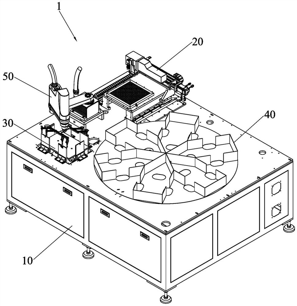
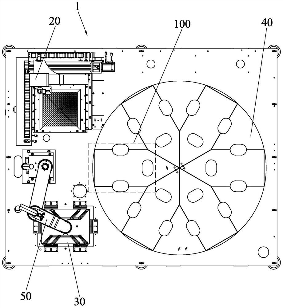
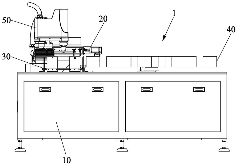
Laser punching equipment
A laser drilling and equipment technology, which is applied in laser welding equipment, welding equipment, metal processing equipment, etc., can solve the problems of poor MARK point marking, low manual operation efficiency, and high labor cost, and achieve high equipment operation consistency and improved Consistency and accuracy in handling, labor cost saving effects
- Summary
- Abstract
- Description
- Claims
- Application Information
AI Technical Summary
Problems solved by technology
Method used
Image

Examples
Embodiment Construction
[0037] In order to further explain the technical solution of the present invention, the present invention will be described in detail below through specific examples.
[0038]In describing the present invention, it should be understood that the terms "center", "longitudinal", "transverse", "upper", "lower", "front", "rear", "left", "right", " Vertical", "horizontal", "top", "bottom", "inner", "outer" and other indication orientations or positional relationships are based on the orientations or positional relationships shown in the drawings, and are only for the convenience of describing the present invention and simplifying Describes, but does not indicate or imply that the device or element referred to must have a specific orientation, be constructed in a specific orientation, and operate in a specific orientation, and therefore should not be construed as limiting the invention. In the description of the present invention, unless otherwise specified, "plurality" means two or ...
PUM
 Abstract
Description
Claims
Application Information