Cutting equipment for automatically adsorbing harmful particles based on environmental protection

A kind of cutting equipment and automatic technology, applied in the direction of metal processing equipment, lighting and heating equipment, parts of lighting devices, etc., can solve the problems of not being able to observe the workpiece in time, cutting completion, excessive waste, etc., and achieve the goal of improving the cutting effect Effect

Active Publication Date: 2020-09-22
台州市路桥广发特鞋业有限公司
View PDF6 Cites 3 Cited by
  • Summary
  • Abstract
  • Description
  • Claims
  • Application Information

AI Technical Summary

Problems solved by technology

[0003] At present, when cutting some workpieces, different fixing structures are often required to fix workpieces with different diameters and shapes, which is troublesome to replace. At the same time, more waste is often generated during the cutting process, and it cannot be repaired in time. processing, some fine particles will directly disperse into the atmosphere, affecting the atmospheric environment. At the same time, due to the complexity of the cutting process, the staff cannot observe in time whether the workpiece is cut. Therefore, in view of this, for the existing structure and The lack of research and improvement, to provide a cutting device based on the automatic adsorption of harmful particles for environmental protection, in order to achieve the purpose of more practical value

Method used


Image

  • Cutting equipment for automatically adsorbing harmful particles based on environmental protection
  • Cutting equipment for automatically adsorbing harmful particles based on environmental protection
  • Cutting equipment for automatically adsorbing harmful particles based on environmental protection

Examples


Embodiment Construction

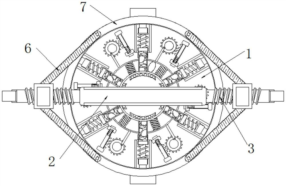
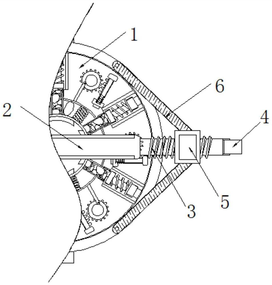
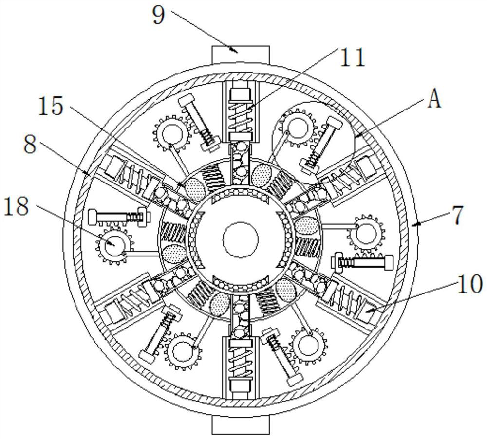
[0021] The present invention will be further described below in conjunction with accompanying drawing:

[0022] as attached figure 1 to attach Figure 6 Shown:

[0023] The invention provides a cutting device based on automatic adsorption of harmful particles for environmental protection, which includes a workbench 1, a support seat 2 is fixedly connected to the surface of the workbench 1, threaded columns 3 are rotatably connected to the left and right sides of the support seat 2, and the support seat The width of 2 is greater than the width of threaded column 3, and the inner wall of threaded sleeve 5 is provided with tooth lines that are compatible with threaded column 3, and one end of threaded column 3 is rotatably connected with rotating rod 4, and the outer surface of threaded column 3 is sleeved with threads The sleeve 5, the outer surface of the threaded sleeve 5 is movably connected with a V-shaped plate 6, the inner side of the V-shaped plate 6 and the upper surfa...


PUM


Abstract

The invention belongs to the technical field of cutting equipment and particularly relates to cutting equipment for automatically adsorbing harmful particles based on environmental protection. A supporting base is fixedly connected to the surface of a workbench, thread columns are rotatably connected to the left and right sides of the supporting base, and a rotation rod is rotatably connected to one end of each thread column. A thread sleeve sleeves the outer surface of each thread column, a V-shaped plate is movably connected to the outer surface of each thread sleeve, an annular base is movably connected to the inner side of each V-shaped plate, of the upper surface of the workbench, an electric conduction plate is arranged in each annular base, and an indicator light is fixedly connected to the outer surface of each annular base. During use, some sweeps generated during a cutting process can be adsorbed and prevented from directly scattering to the atmosphere, the cutting equipmenthas a certain environmental protection effect, when retractable columns are pressed, compression bodies can be driven to be compressed, a spraying solution in the compression bodies can be sprayed tothe surface of a workpiece so as to cool the workpiece, and the effect of cutting the workpiece is greatly improved.

Description

technical field [0001] The invention belongs to the technical field of cutting equipment, and in particular relates to a cutting equipment based on automatic adsorption of harmful particles for environmental protection. Background technique [0002] Steel is used in various industries such as construction and machinery, and steel wire is one of the steel products. Because users have different requirements for the length and thickness of the steel wire, the steel wire is not cut after being produced, but rolled into a coil, and then straightened and cut when used. Straightening and cutting equipment is the equipment used to complete the process of straightening and cutting steel wire. [0003] At present, when cutting some workpieces, different fixing structures are often required to fix workpieces with different diameters and shapes, which is troublesome to replace. At the same time, more waste is often generated during the cutting process, and it cannot be repaired in time...

Claims


Application Information

Patent Timeline
Patent Type & Authority Applications(China)
IPC IPC(8): B23Q11/00B23Q11/10B23Q3/06F21V33/00
CPCB23Q3/06B23Q11/00B23Q11/0042B23Q11/10F21V33/00
Inventor 吕峰
Owner 台州市路桥广发特鞋业有限公司
Why Eureka
Try Eureka