Connecting rod jig capable of changing angle

A technology of changing angles and fixtures, applied in the direction of manufacturing tools, workpiece clamping devices, etc., can solve the problems of increased failure rate, complex fixture structure, increased labor force, etc., to reduce the cost of fixtures, reduce the weight of fixtures, reduce The effect of maintenance difficulty

Pending Publication Date: 2020-09-22
伯朗特机器人股份有限公司
View PDF0 Cites 0 Cited by
  • Summary
  • Abstract
  • Description
  • Claims
  • Application Information

AI Technical Summary

Problems solved by technology

[0002] At present, in the production workshop, the welding, dispensing, and screwing of product workpieces are assembled by manual positioning or controlled by multiple power mechanisms; manual positioning and assembly according to working conditions increases labor and is extremely low in efficiency; multi-power Mechanism control assembly will lead to high cost, complex fixture structure, and due to the complex structure, the failure rate will increase accordingly

Method used


Image

  • Connecting rod jig capable of changing angle
  • Connecting rod jig capable of changing angle
  • Connecting rod jig capable of changing angle

Examples


Embodiment Construction

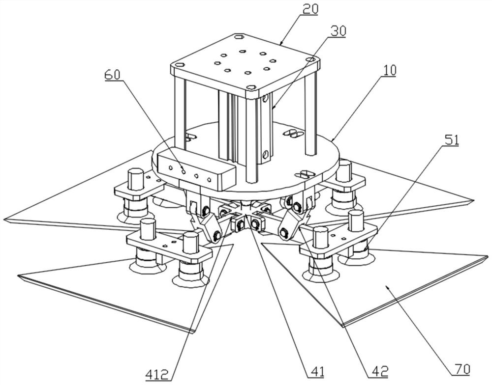
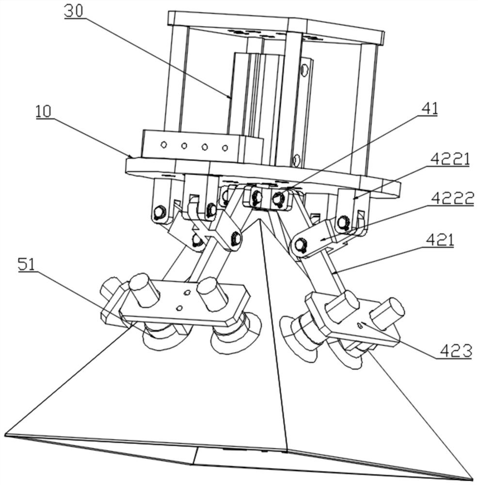
[0030] see Figure 1 to Figure 3 , a connecting rod fixture whose angle can be changed in this embodiment includes a fixture plate 10, a fixed mounting plate 20, a drive source 30, a transmission device, four groups of adsorption components and a gas distribution block 60;

[0031] Specifically, the fixture plate 10 is installed on the fixed mounting plate 20, and the fixed mounting plate 20 can be connected with an external manipulator (not shown);

[0032] Specifically, the driving source 30 of this embodiment is preferably a cylinder;

[0033] Specifically, the driving source 30 is arranged on the fixture plate 10;

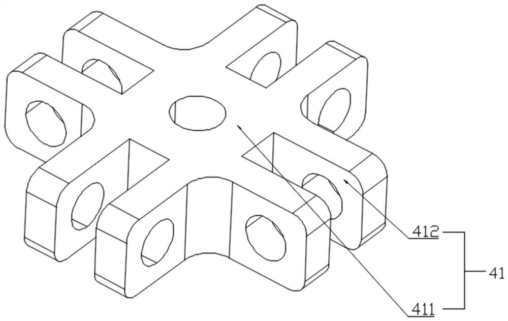
[0034] Specifically, the transmission device includes a first connecting member 41 and four sets of link mechanisms 42; the first connecting member 41 is arranged on the output end of the drive source 30; the input ends of each set of link mechanisms 42 are Hinged with the first connector 41;

[0035] More specifically, the first connector 41 includes a main...


PUM


Abstract

The invention relates to a connecting rod jig capable of changing the angle. The connecting rod jig comprises a jig plate, a drive source, a transmission device and adsorption part sets. The drive source is arranged on the jig plate. The transmission device comprises a first connecting part and at least two groups of connecting rod mechanisms. The first connecting part is arranged at the output end of the drive source. The input end of each group of connecting rod mechanism is hinged to the first connecting part. Each absorption part set is arranged at the output end of one group of connectingrod mechanism. The drive source drives the first connecting part to do feeding movement along the axis of the first connecting part and then drives all the connecting rod mechanisms to do rotationalmovement, and the rotation working face of each connecting rod mechanism is parallel to the axis of the first connecting part. All workpieces are spliced and positioned through one drive source, the number of drive sources and fixing parts is effectively reduced, the weight of the jig is reduced, and then the cost of the jig is reduced; and meanwhile as only one drive source is adopted, the faultrate of the machine is greatly reduced, and the maintenance difficulty and cost are reduced.

Description

technical field [0001] The invention relates to the technical field of tooling fixtures, in particular to a connecting rod fixture whose angle can be changed. Background technique [0002] At present, in the production workshop, the welding, dispensing, and screwing of product workpieces are assembled by manual positioning or controlled by multiple power mechanisms; manual positioning and assembly according to working conditions increases labor and is extremely low in efficiency; multi-power Mechanism-controlled assembly will lead to high cost, complex fixture structure, and due to the complex structure, the failure rate will increase accordingly. [0003] Therefore, it is necessary to provide a connecting rod jig with simple structure and stable operation which can change the angle. SUMMARY OF THE INVENTION [0004] Based on this, the object of the present invention is to overcome the shortcomings and deficiencies in the prior art, and provide a connecting rod jig that c...

Claims


Application Information

Patent Timeline
Patent Type & Authority Applications(China)
IPC IPC(8): B25B11/00
CPCB25B11/00B25B11/002B25B11/005
Inventor 洪宏彬
Owner 伯朗特机器人股份有限公司
Why Eureka
Try Eureka