
Hydraulic driven three-degree-of-freedom robot joint

A robot joint and degree of freedom technology, applied in the field of robotics, can solve problems such as extremely high wiring requirements, complex structure, and limited load-to-weight ratio of robot joints

Pending Publication Date: 2020-09-22
THE 21TH RES INST OF CHINA ELECTRONIC TECH GRP CORP
View PDF7 Cites 4 Cited by
  • Summary
  • Abstract
  • Description
  • Claims
  • Application Information

AI Technical Summary

Problems solved by technology

However, this electric drive method has extremely high requirements for wiring, and the structure is relatively complicated; limited by the structure and self-weight of the motor and reducer, the load-to-weight ratio of the robot joint is limited. often underpowered

Method used


Image

  • Hydraulic driven three-degree-of-freedom robot joint
  • Hydraulic driven three-degree-of-freedom robot joint
  • Hydraulic driven three-degree-of-freedom robot joint

Examples


Embodiment Construction

[0026] The technical solutions in the embodiments of the present invention will be clearly and completely described below. Obviously, the described embodiments are only a part of the embodiments of the present invention, rather than all the embodiments. Based on the embodiments of the present invention, all other embodiments obtained by those of ordinary skill in the art fall within the protection scope of the present invention.

[0027] In the description of the present invention, the terms "longitudinal", "horizontal", "upper", "lower", "front", "rear", "left", "right", "vertical", "horizontal", " The orientation or positional relationship indicated by "top", "bottom", etc. is based on the orientation or positional relationship shown in the drawings, which is only for the convenience of describing the present invention rather than requiring that the present invention must be constructed and operated in a specific orientation, so it cannot be understood as Restrictions on the in...


PUM


Abstract

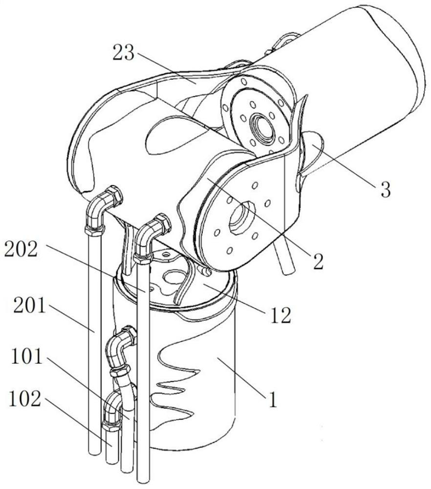
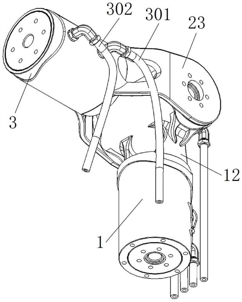
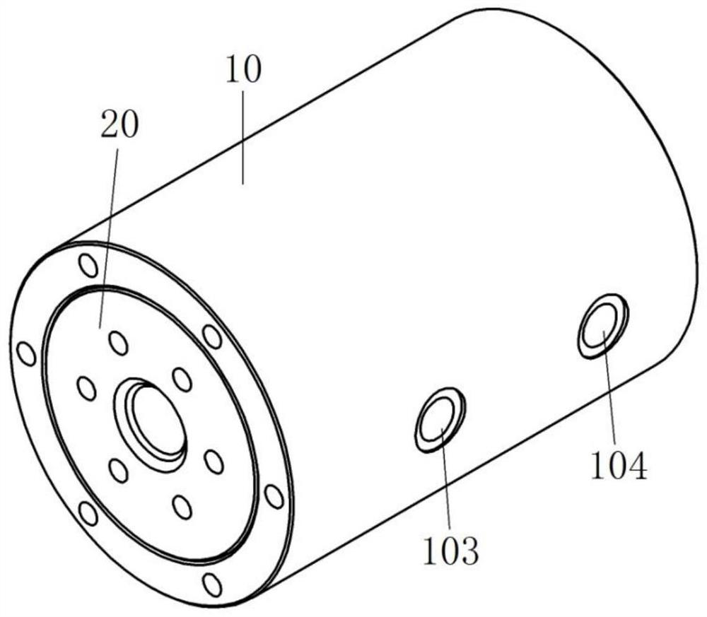
The invention provides a hydraulic driven three-degree-of-freedom robot joint. The three-degree-of-freedom robot joint comprises a first hydraulic rotation cylinder, a second hydraulic rotation cylinder, a third hydraulic rotation cylinder, a first connecting frame and a second connecting frame. Each of the three hydraulic rotation cylinders comprises an outer shell and a cylinder block, and the cylinder block rotates relative to the outer shell. The cylinder block connecting end of the first connecting frame is fixed to the cylinder block of the first hydraulic rotation cylinder. The outer shell connecting end of the first connecting frame is fixed to the outer shell of the second hydraulic rotation cylinder. The cylinder block connecting end of the second connecting frame is fixed to thecylinder block of the second hydraulic rotation cylinder. The outer shell connecting end of the second connecting frame is fixed to the outer shell of the third hydraulic rotation cylinder. Comparedwith motors and speed reducers, the hydraulic rotation cylinders have the lower weight, so that the overall weight of the robot joint is reduced, and the lightweight design of the robot joint is realized. Moreover, the hydraulic rotation cylinder for hydraulic driving can provide large torque, and the design of the high-load self-weight ratio of a robot is realized.

Description

Technical field [0001] The invention belongs to the technical field of robots, and specifically relates to a hydraulically driven three-degree-of-freedom robot joint. Background technique [0002] In the field of robotics, lightweight robots have gradually become the market leader, and robots with high load-to-weight ratios are the development direction of technology. As an important part of robots, robot joints play an important role in robots. The performance of robot joints has an important influence on the ratio of weight to weight of the robot, the accuracy and speed of the robot. [0003] Traditional robot joints are all electrically driven, that is, a mode that uses a motor and a reducer to achieve the motion of the robot joints. However, this kind of electric drive has extremely high requirements for wiring, and the structure is more complicated; limited by the structure and weight of the motor and reducer, the load-to-weight ratio of the robot joint is limited, and the r...

Claims


Application Information

Patent Timeline
Patent Type & Authority Applications(China)
IPC IPC(8): B25J17/02
CPCB25J17/02
Inventor 王卫军谢天蔡松涛王子荣何春来
Owner THE 21TH RES INST OF CHINA ELECTRONIC TECH GRP CORP
Learn More