Magnet assembling device and magnet supplying equipment and material stripping mechanism thereof

A magnet and stripping technology, applied in the field of automation, can solve problems such as low operating efficiency, high labor costs, and bulky magnet assembly equipment, and achieve the effects of reducing labor costs, improving operating efficiency, and realizing automated operations

Active Publication Date: 2020-09-22
HONGFUJIN PRECISION ELECTRONICS ZHENGZHOU
View PDF11 Cites 2 Cited by
  • Summary
  • Abstract
  • Description
  • Claims
  • Application Information

AI Technical Summary

Problems solved by technology

[0004] However, due to the small size of the small magnets 8 and the relatively heavy magnet assembly equipment, a large amount of manpower needs to be configured at the magnet assembly station to take the small magnets 8 out of the magazine 7 and place them Feed it into this magnet assembly equipment which is inefficient and labor costly

Method used


Image

  • Magnet assembling device and magnet supplying equipment and material stripping mechanism thereof
  • Magnet assembling device and magnet supplying equipment and material stripping mechanism thereof
  • Magnet assembling device and magnet supplying equipment and material stripping mechanism thereof

Examples


Embodiment Construction

[0047] The technical solutions in the embodiments of the present invention will be clearly and completely described below in conjunction with the accompanying drawings in the embodiments of the present invention. Obviously, the described embodiments are only part of the embodiments of the present invention, not all of them. Based on the implementation manners in the present invention, all other implementation manners obtained by persons of ordinary skill in the art without making creative efforts belong to the scope of protection of the present invention.

[0048] It should be noted that when an element is referred to as being “fixed” to another element, it can be directly on the other element or there can also be an intervening element. When an element is referred to as being "connected to" another element, it can be directly connected to the other element or intervening elements may also be present. When an element is referred to as being "disposed on" another element, it ca...


PUM


Abstract

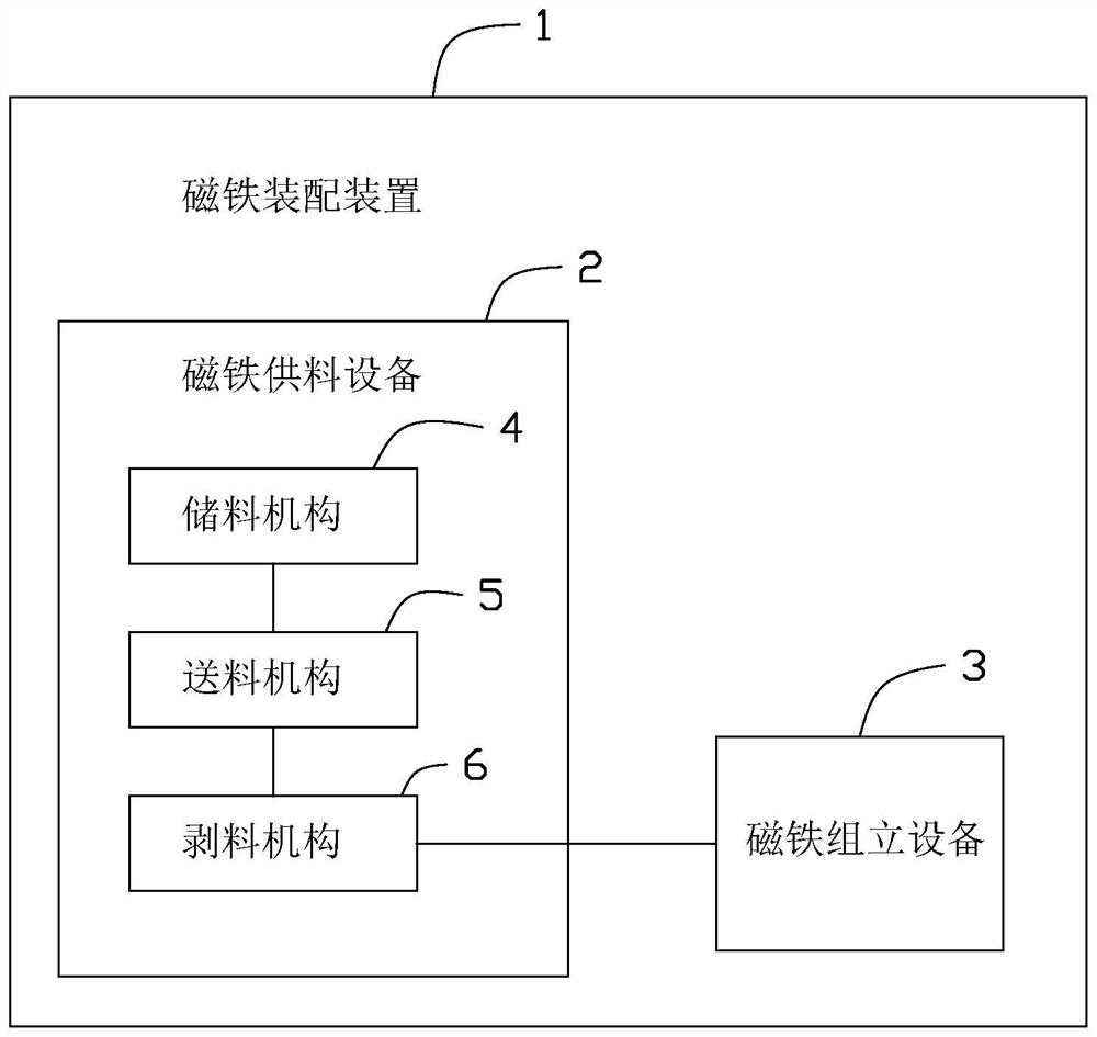
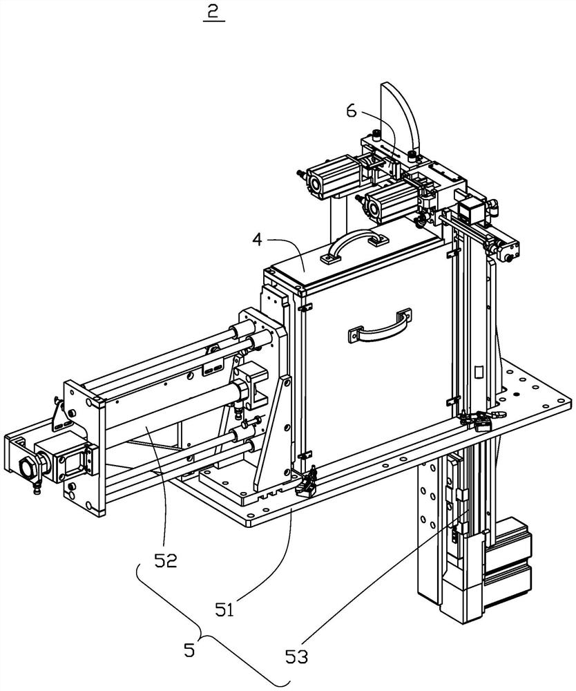
The invention provides a material stripping mechanism. The mechanism comprises a main body, a material pushing module, a material stripping module, a material blowing module, a discharging module anda discharging shade. The main body comprises a feeding part, a discharging part, a material guiding part and a material stripping part. The feeding part is arranged on the discharging part and is positioned on the lower part of the discharging part. The material guiding part and the material stripping part are respectively arranged at two opposite ends of the feeding part, and the material stripping part is in butt joint with the discharging part at the same time. The feeding part is used for receiving incoming materials. The material pushing module is used for pushing the incoming materials received by the feeding part to the material stripping part. The material stripping module is used for unplugging two rubber plugs of the incoming materials in the material stripping part and pushing amaterial box with the two rubber plugs unplugged together with small magnet pieces in the material box to the material blowing module. The material blowing module is used for blowing the small magnetpieces out of the material box and into the discharging part, and blowing an empty material box to the discharging shade. The discharging module is used for pushing the small magnet pieces out of thedischarging part. A material stripping mechanism can realize automatic stripping of the small magnet pieces. The invention further provides magnet supplying equipment and a magnet assembling device.

Description

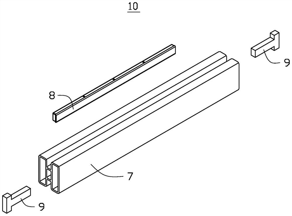
technical field [0001] The invention relates to the technical field of automation, in particular to an automatic magnet assembly device, magnet feeding equipment and a stripping mechanism thereof. Background technique [0002] In the processing and manufacturing industry, the edge of electronic products needs to be assembled with small magnets. Small magnets are generally stored in corresponding magazines when they are transported in the workshop. Such as figure 1 As shown, the incoming material 10 includes a hollow material box 7, a small magnet 8 accommodated in the material box 7 and two rubber plugs 9, and the two rubber plugs 9 block the two ends of the material box 7 respectively. The opening is used to seal the magnet small piece 8 . [0003] In the existing assembly work, the manual operation mode is generally adopted, that is, the small magnet piece 8 is manually taken out from the magazine 7, and then the small magnet piece 8 is sent into the magnet assembly equ...

Claims


Application Information

Patent Timeline
Patent Type & Authority Applications(China)
IPC IPC(8): B65G47/82B23P19/00
CPCB65G47/82B23P19/001
Inventor 李世友张一健
Owner HONGFUJIN PRECISION ELECTRONICS ZHENGZHOU
Why Eureka
Try Eureka