Axial positioning device of spline transmission shaft
A technology of axial positioning and transmission shaft, which is applied in the field of transmission system, can solve the problems such as difficult to meet the maintainability of the transmission system, affect the disassembly efficiency of various components of the transmission system, and the transmission shaft is not easy to disassemble, etc., to achieve a compact structure layout, Easy disassembly and good maintainability
- Summary
- Abstract
- Description
- Claims
- Application Information
AI Technical Summary
Problems solved by technology
Method used
Image
Examples
Embodiment 1
[0023] This embodiment provides an axial positioning device for a spline transmission shaft, which can be easily disassembled and assembled under the condition of ensuring the function of the transmission shaft, so that the transmission system has better maintainability, and can meet the needs of high power density and modularity. The structural layout is compact under the requirements of the research and development of the modernized transmission system.
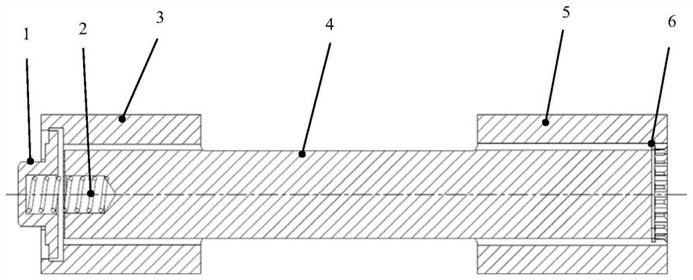
[0024] like Figure 1-3 As shown, the axial positioning device axially positions the spline drive shaft 4, including: a limit sleeve 1, a spring 2, an inner spline sleeve A3, an inner spline sleeve B5 and a snap ring 6;
[0025] The two ends of the spline transmission shaft 4 are respectively connected to the external structural parts through the internal spline sleeve A3 and the internal spline sleeve B5, which can realize the power transmission of the spline transmission shaft 4 to the external structural parts; the end w...
Embodiment 2
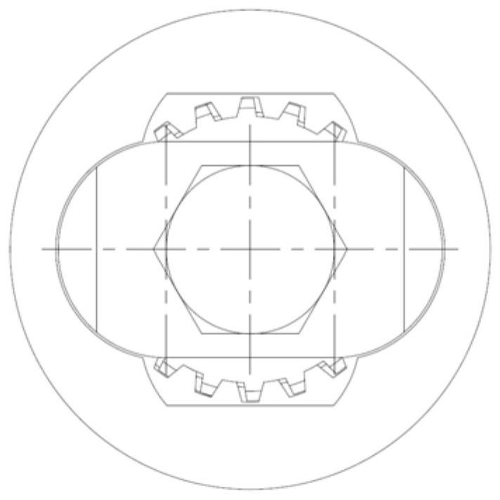
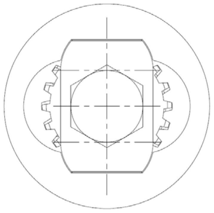
[0030] On the basis of Example 1, such as Figure 4-6 As shown, the inner hole groove at the left end of the inner spline sleeve A3 includes: an annular groove and a special-shaped hole. The diameter of the hole is between the maximum diameter and the minimum diameter of the oval hole, and the maximum diameter of the special-shaped hole of the inner spline sleeve B5 is the same as the inner diameter of the annular groove, so that the limit sleeve 1 can be installed from the maximum diameter of the special-shaped hole. It enters the inner hole groove of the inner spline sleeve A3, and is locked and locked after being rotated at a set angle; among them, the specific setting of the inner hole groove is conducive to realizing the relative inner hole of the limit sleeve without adding other mechanical structures. Locking and unlocking of spline sleeve A.
PUM
 Abstract
Description
Claims
Application Information
 - R&D
- Intellectual Property
- Life Sciences
- Materials
- Tech Scout
- Unparalleled Data Quality
- Higher Quality Content
- 60% Fewer Hallucinations
Browse by: Latest US Patents, China's latest patents, Technical Efficacy Thesaurus, Application Domain, Technology Topic, Popular Technical Reports.
© 2025 PatSnap. All rights reserved.Legal|Privacy policy|Modern Slavery Act Transparency Statement|Sitemap|About US| Contact US: help@patsnap.com


