Control system and method for synchronous temporary locking of flexible DC valve bank

A flexible DC and valve group control technology, applied in the direction of power transmission AC network, electrical components, emergency protection circuit devices, etc., can solve the problem that the communication architecture cannot adapt to UHV flexible straight

Active Publication Date: 2020-09-22
ELECTRIC POWER RESEARCH INSTITUTE, CHINA SOUTHERN POWER GRID CO LTD +1
View PDF7 Cites 0 Cited by
  • Summary
  • Abstract
  • Description
  • Claims
  • Application Information

AI Technical Summary

Problems solved by technology

For this reason, it is very necessary to implement synchronous temporary blocking of A and B valve groups, and the current communication architecture of conventional UHV DC control and protection systems cannot meet the needs of UHV DC

Method used


Image

  • Control system and method for synchronous temporary locking of flexible DC valve bank
  • Control system and method for synchronous temporary locking of flexible DC valve bank
  • Control system and method for synchronous temporary locking of flexible DC valve bank

Examples


Embodiment Construction

[0032] The following will clearly and completely describe the technical solutions in the embodiments of the present invention with reference to the accompanying drawings in the embodiments of the present invention. Obviously, the described embodiments are only some, not all, embodiments of the present invention. Based on the embodiments of the present invention, all other embodiments obtained by persons of ordinary skill in the art without creative efforts fall within the protection scope of the present invention.

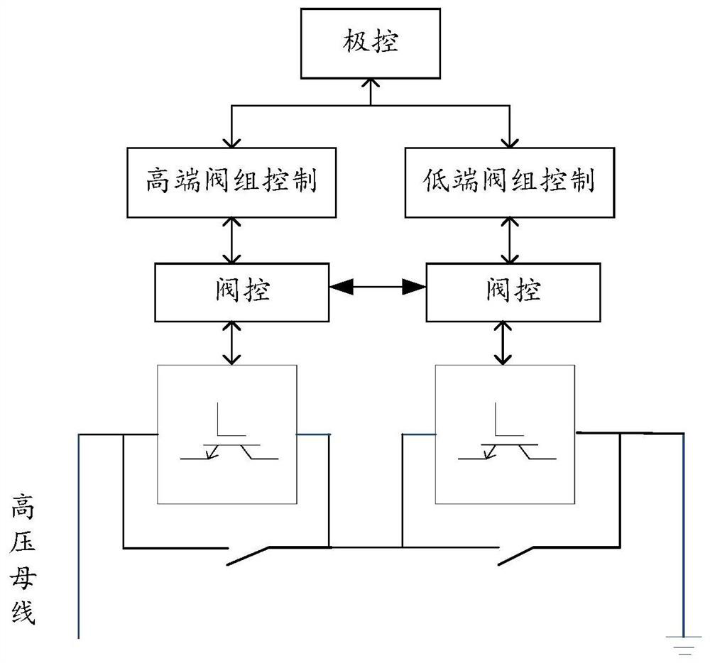
[0033] see figure 1 , is a schematic diagram of a control system for synchronous temporary locking of flexible DC valve groups provided by an embodiment of the present invention. The control system includes extreme control, high-end valve group control, low-end valve group control, high-end valve control and low-end valve control; wherein, the extreme control is connected with the high-end valve group control and the low-end valve group control respectively, the hi...


PUM


Abstract

The invention discloses a control system and method for synchronous temporary locking of a flexible DC valve bank, and the method comprises the steps that the valve bank control of a first valve banktransmits an enable signal to a corresponding first valve bank according to the operation state of a second valve bank provided by pole control and the operation state of the first valve bank; if thefirst valve controller judges that the first valve bank is triggered to be temporarily locked according to the bridge arm current, a temporary locking signal is sent to a second valve controller; thesecond valve bank performs AND operation according to an enable signal and a temporary locking signal received by the second valve bank; whether to execute synchronous temporary locking or not is judged according to the AND operation result; if the AND operation result is yes, the synchronous temporary locking is executed; if the AND operation result is negative, the synchronous temporary lockingis not executed. By adding the communication connection between the valve control hosts, mutual transmission of temporary locking signals between the valve control hosts is achieved, and synchronous temporary locking of the high-end valve bank and the low-end valve bank is achieved.

Description

technical field [0001] The invention relates to the technical field of high-voltage direct current transmission, in particular to a control system and method for synchronously and temporarily blocking high-end and low-end valve groups of ultra-high voltage flexible direct current. Background technique [0002] In the conventional UHV DC control and protection system architecture, there is a high-speed communication connection between the pole control and the high-end valve group control and low-end valve group control of the pole, and there is generally no need for communication between the high-end and low-end valve group controls of the pole, even if there is Only for backup communication; and there is no communication between the valve controllers of the same extreme high-end valve group and low-end valve group, and only need to execute the trigger signal issued by the respective valve group control. The trigger pulses of the high-end valve group and the low-end valve gro...

Claims


Application Information

Patent Timeline
Patent Type & Authority Applications(China)
IPC IPC(8): H02H7/26H02J3/36
CPCH02H7/262H02H7/268H02J3/36Y02E60/60
Inventor 李书勇郭琦饶宏李岩林雪华陈钦磊陈德扬刘志江曾冠铭
Owner ELECTRIC POWER RESEARCH INSTITUTE, CHINA SOUTHERN POWER GRID CO LTD
Why Eureka
Try Eureka