Quick locker for motor junction box

A fast locking and junction box technology, applied in the direction of electrical components, electromechanical devices, electric components, etc., can solve problems such as shortening maintenance time, affecting maintenance progress, water vapor weight, etc., and achieves the effect of facilitating daily maintenance work and daily maintenance

Pending Publication Date: 2020-09-22
JIANGYIN XINGCHENG SPECIAL STEEL WORKS CO LTD
View PDF0 Cites 2 Cited by
  • Summary
  • Abstract
  • Description
  • Claims
  • Application Information

AI Technical Summary

Problems solved by technology

[0002] At present, the production rhythm of steel mills is fast, and the maintenance is often canceled or shortened due to the large output. In normal repairs, it is also race against time. In such a situation, the pressure is quite huge for the maintenance personnel, especially the roller table motor. When checking and opening the cover for the first time, due to the huge quantity, it takes a lot of time to unscrew the fixing screws on the cover of the junction box each time, which seriously affects the maintenance progress
[0003] The existing motor junction boxes are fixed with four screws, some are hexagonal, some are hexagonal, and some are cross-shaped. The tool wrench, hexagonal, and screwdriver needed may not be made into a uniform specification due to different requirements. , our maintenance personnel have to bring all kinds of tools to the site for disassembly and assembly, and due to the heavy water vapor, the screws are rusted, and the paint is not painted regularly, which leads to the inability to screw them out smoothly without some auxiliary means. When the motor needs to be opened for inspection, it takes a lot of time to open the cover, which seriously affects the maintenance progress and wastes manpower

Method used


Image

  • Quick locker for motor junction box
  • Quick locker for motor junction box
  • Quick locker for motor junction box

Examples


Embodiment Construction

[0044] The present invention will be further described in detail below in conjunction with the accompanying drawings and embodiments.

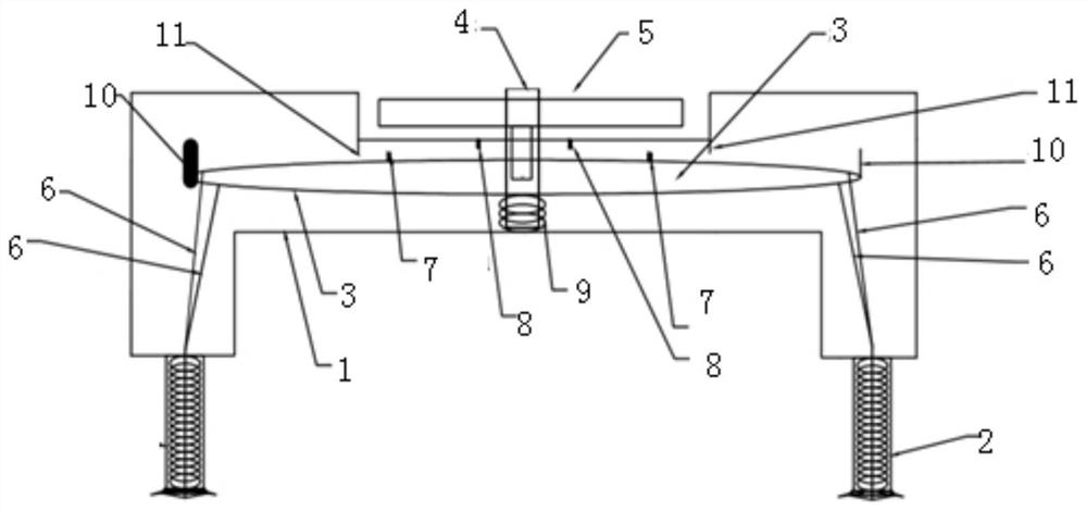
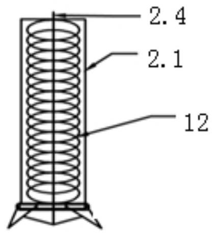
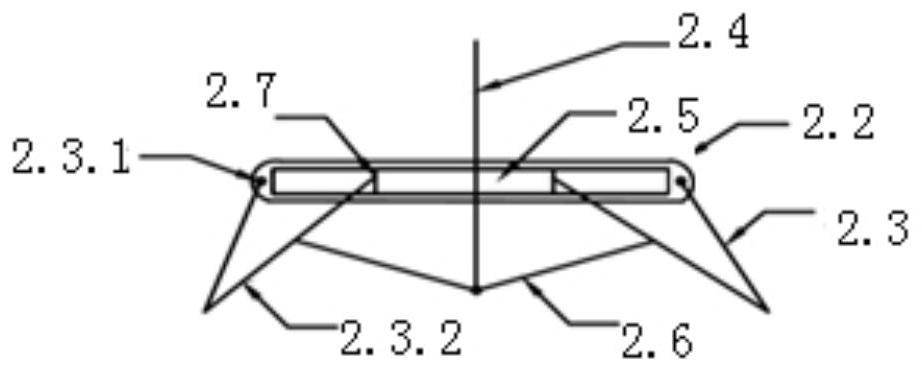
[0045] Such as Figure 1-4 As shown, the present invention relates to a quick locker for a motor junction box, including a case 1, which can be used as a cover of the junction box, and is covered on the base of the junction box, and the bottom of the case 1 is respectively Four locking devices 2 are provided, and the locking devices 2 correspond to the four screw holes on the junction box, and can be inserted into the screw holes, and the locker is fixed on the junction box through the action of the locking devices 2 .

[0046] An elliptical turntable 3 is horizontally arranged inside the case 1, and the center position of the ellipse turntable 3 is fixed at the center position inside the case 1 by a fixed rod 4. The upper end of the fixed rod 4 extends out of the case 1 and is installed The manual wheel 5 is connected to the elliptical turnt...


PUM


Abstract

The invention relates to a quick locker for a motor junction box, and the quick locker comprises a housing covering a junction box base, a locking device corresponding to a junction box screw hole isarranged at the bottom of the housing; the quick locker is fixed on the junction box under the action of the locking device; an elliptical rotary table is horizontally arranged in the housing; the elliptical rotary table is fixed in the housing through a fixing rod; the upper end of the fixing rod extends out of the housing and then is provided with a manual rotating wheel; the manual rotating wheel is connected with the elliptical rotary tables, the manual rotating wheel can rotate relative to the fixing rod, the elliptical rotary tables located at the two ends of the long shaft are connectedwith the locking device through the pull wires, the pull wires are pulled in and loosened by rotating the elliptical rotary tables in the forward direction or the reverse direction, and therefore thejunction box is locked and unlocked by the locking device. According to the invention, the junction box can be opened and closed quickly without any tool, so maintenance personnel can disassemble andconnect wires of the motor quickly, and daily maintenance work is facilitated.

Description

technical field [0001] The invention belongs to the technical field of motors, and in particular relates to a quick locker for a motor junction box. Background technique [0002] At present, the production rhythm of steel mills is fast, and the maintenance is often canceled or shortened due to the large output. In normal repairs, it is also race against time. In such a situation, the pressure is quite huge for the maintenance personnel, especially the roller table motor. When checking and opening the cover for the first time, due to the huge number, it takes a lot of time to twist the fixing screws on the junction box cover each time, which seriously affects the maintenance progress. [0003] The existing motor junction boxes are fixed with four screws, some are hexagonal, some are hexagonal, and some are cross-shaped. The tool wrench, hexagonal, and screwdriver needed may not be made into a uniform specification due to different requirements. , our maintenance personnel ha...

Claims


Application Information

Patent Timeline
Patent Type & Authority Applications(China)
IPC IPC(8): H02K5/22
CPCH02K5/225
Inventor 周凯吴锋李敏金均刘静忠张磊汤莲钧黄栋顾君
Owner JIANGYIN XINGCHENG SPECIAL STEEL WORKS CO LTD
Why Eureka
Try Eureka