Transponder monitoring device

A monitoring device and transponder technology, which is applied in the field of transponder detection, can solve problems such as inaccurate transponder detection, and achieve the effects of reducing labor costs, accurate monitoring results, and low cost

Active Publication Date: 2020-09-22
CHINA RAILWAY DESIGN GRP CO LTD
View PDF8 Cites 5 Cited by
  • Summary
  • Abstract
  • Description
  • Claims
  • Application Information

AI Technical Summary

Problems solved by technology

[0007] The purpose of the present invention is to provide a transponder monitoring device to solve the problem of inaccurate transponder detection in the prior art

Method used


Image

  • Transponder monitoring device
  • Transponder monitoring device
  • Transponder monitoring device

Examples


Embodiment Construction

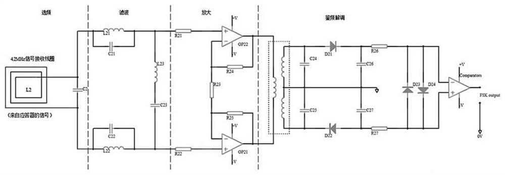
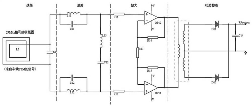
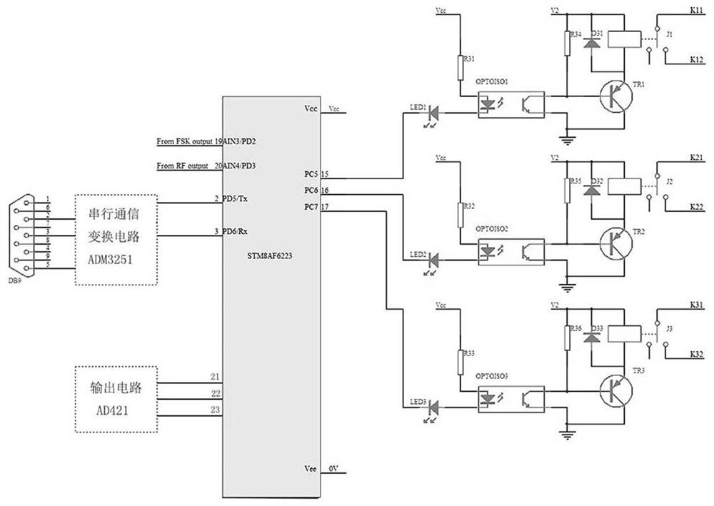
[0037] The device of the invention includes a first frequency selection filter amplifier circuit, a frequency discrimination demodulation circuit, a second frequency selection filter amplifier circuit, a wave detection rectifier circuit, a microprocessor and an output circuit.

[0038] Such as figure 1 As shown, the first frequency-selective filter amplifying circuit is coupled with the frequency-discrimination demodulation circuit, and is used to receive the electromagnetic wave signal sent by the transponder, perform frequency-selective filtering and amplification, and send it to the frequency discrimination demodulation circuit. The first frequency selection filter amplifying circuit is to receive the electromagnetic wave signal sent by the transponder after the inductance L2 and the capacitor C2 are connected in parallel, one end is connected in parallel with the inductance L21 and the capacitor C21, the resistor R21 and the non-inverting input end of the operational amplifie...


PUM


Abstract

The invention relates to a transponder monitoring device. The transponder monitoring device comprises a first frequency selection filtering amplification circuit, a frequency discrimination demodulation circuit, a second frequency selection filtering amplification circuit, a detection rectification circuit, a microprocessor and an output circuit, the first frequency selection filtering amplification circuit receives an electromagnetic wave signal emitted by the transponder; electromagnetic wave signals emitted by a vehicle-mounted BTM are received through the second frequency selection filtering amplification circuit, the transponder and the vehicle-mounted BTM can be monitored in real time, an oscilloscope does not need to be carried to manually check the transponder and the vehicle-mounted BTM one by one, the working state of an original facility is not changed, even if an extreme special event occurs, the detection device can be controlled to be in a non-working state, and the normal work of the transponder and the vehicle-mounted BTM is not influenced. The transponder monitoring device has no an electromagnetic-wave oscillation circuit, only receives the BTM and the radio frequency signals of the transponder, does not radiate or leak the radio frequency signals to the outside, does not interfere with other external facilities, needs to add a small number of peripheral components on the basis of original equipment, and is low in cost.

Description

technical field [0001] The invention relates to the technical field of transponder detection, in particular to a transponder monitoring device. Background technique [0002] Traditional railways bury signs indicating railway line parameters on the side of the railway for train drivers to visually watch. Due to the high speed of the high-speed railway, the visual line signs on the side of the railway are no longer suitable. In order to overcome this shortcoming, at this stage, the train control system is upgraded to automatically read the electronic signs that store the parameters of the railway line. The high-speed train control system includes two parts: ground equipment and on-board equipment. The transponder is one of the important components of the ground equipment, and the vehicle-mounted transponder information receiving module (vehicle BTM) is one of the important components of the vehicle-mounted equipment. [0003] China Train Control System has 5 application leve...

Claims


Application Information

Patent Timeline
Patent Type & Authority Applications(China)
IPC IPC(8): H04B5/00
CPCH04B5/0068
Inventor 熊飞
Owner CHINA RAILWAY DESIGN GRP CO LTD
Why Eureka
Try Eureka