Plaster bandage water injection equipment for orthopedic limb fixation

A technology for plaster bandages and water injection equipment, which is applied in plaster bandages, non-adhesive dressings, dressings, etc., which can solve the problems of slow degassing, time-consuming and energy-consuming, and achieve the effect of preventing falling

Inactive Publication Date: 2020-09-25
HEBI CITY PEOPLES HOSPITAL
View PDF8 Cites 4 Cited by
  • Summary
  • Abstract
  • Description
  • Claims
  • Application Information

AI Technical Summary

Problems solved by technology

[0003] At present, putting plaster bandages into water for soaking is usually done manually by nurses. Nurses manually fold a certain amount of plaster bandages to a certain thickness repeatedly, and then soak them in water. In order to quick

Method used


Image

  • Plaster bandage water injection equipment for orthopedic limb fixation
  • Plaster bandage water injection equipment for orthopedic limb fixation
  • Plaster bandage water injection equipment for orthopedic limb fixation

Examples


Embodiment 1

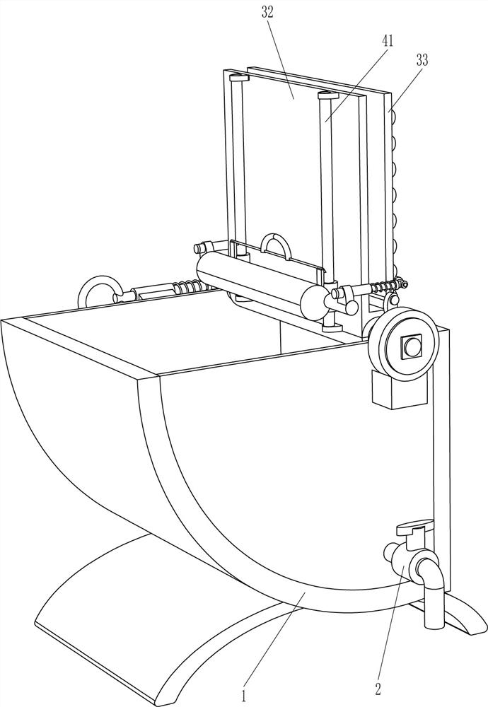
[0024] A plaster bandage water injection device for orthopedic limb fixation, such as Figure 1-3 As shown, it includes a water tank 1, a drain valve 2, a clamping mechanism 3 and a pressing mechanism 4. The lower part of the front side of the water tank 1 is connected with the drain valve 2. The right side of the top of the water tank 1 is equipped with a clamping mechanism 3. A pressing mechanism 4 is installed.

[0025] The clamping mechanism 3 includes a rotating shaft 31, a splint 32, a hinge plate 33 and an arc contact plate 34. The right side of the top of the water tank 1 is rotationally connected with a rotating shaft 31, and the rotating shaft 31 is connected with a splint 32, and the right side of the splint 32 is hingedly connected with a The hinge plate 33 is connected with a plurality of arc-shaped contact plates 34 evenly spaced on the right side of the hinge plate 33 .

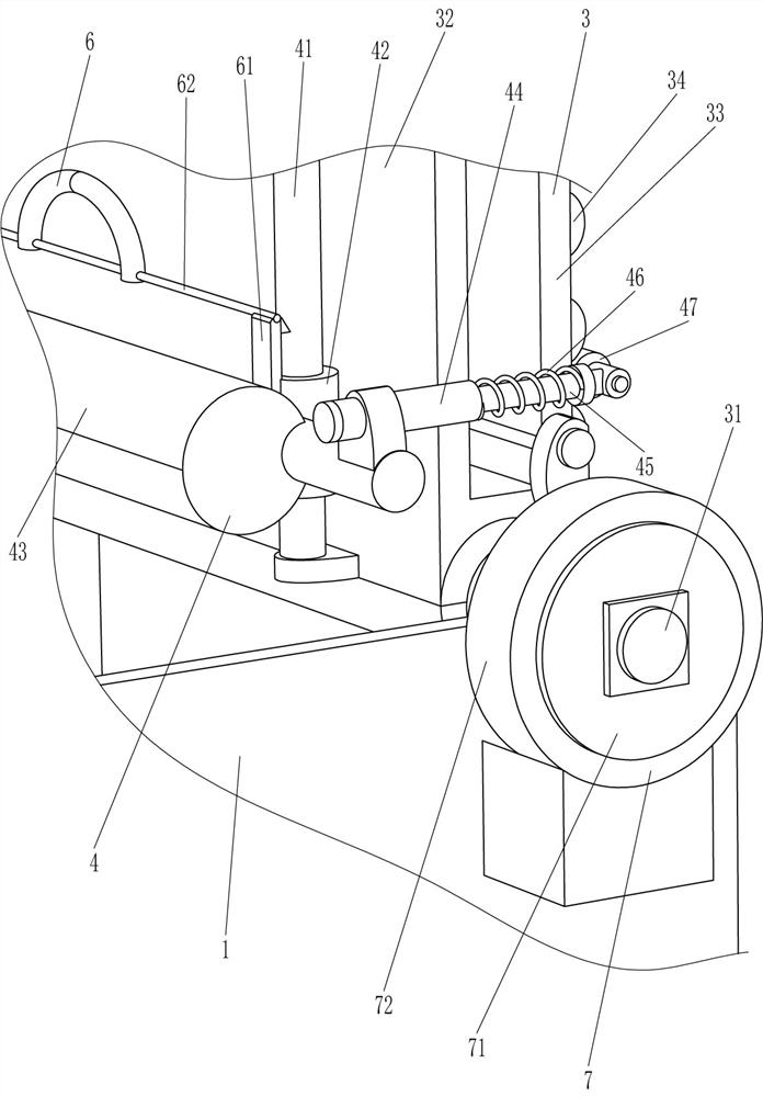
[0026] The pressing mechanism 4 includes a guide rod 41, a guide sleeve 42, a counterweigh...

Embodiment 2

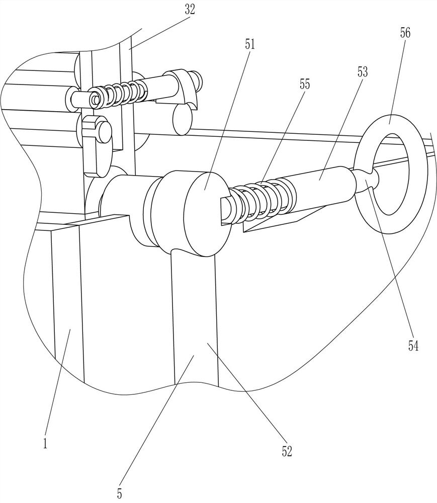
[0029] On the basis of Example 1, such as image 3 and Figure 4 As shown, an anti-turnover mechanism 5 is also included. The anti-turnover mechanism 5 includes a grooved plate 51, a rocker 52, a guide tube 53, a latch 54, a second spring 55 and a pull ring 56, and the rear end of the rotating shaft 31 is connected with a groove Disk 51, grooved disk 51 is connected with rocking handle 52, the rear side of water tank 1 on the left side of grooved disk 51 is connected with guide pipe 53, inside guide pipe 53 is connected with latch 54 slidingly, and latch 54 is inserted in grooved disk 51 A second spring 55 is connected to the latch 54 , the left end of the second spring 55 is connected to the right end of the guide tube 53 , and the left end of the latch 54 is connected to a pull ring 56 .

[0030] Initially, the latch 54 is inserted in the grooved disc 51, and the grooved disc 51 is fixed, so that the rotating shaft 31 can be fixed to prevent the rotating shaft 31 from rotat...

Embodiment 3

[0032] On the basis of Example 2, such as figure 2 As shown, a locking mechanism 6 is also included. The locking mechanism 6 includes an elastic hook 61 and a connecting rod 62. Two elastic hooks 61 are connected to the weight bar 43 between the two sliding sleeves 44. The two elastic hooks 61 front and rear Symmetrically, a connecting rod 62 is connected between the top ends of the two elastic hooks 61 .

[0033] When the counterweight bar 43 moves down to a low place in the water tank 1, the elastic hook 61 can be hooked on the guide rod 41, so that the counterweight bar 43 can be fixed to prevent the splint 32 from rotating clockwise to the upper side of the water tank 1 The counterweight bar 43 moves, thereby can fix the contact roller 47, prevent the contact roller 47 from moving, and then can realize the fixing of the hinge plate 33, prevent the hinge plate 33 from opening; it can prevent the splint 32 from rotating clockwise to the upper side of the water tank 1 , the...


PUM


Abstract

The invention relates to plaster bandage water injection equipment, in particular to plaster bandage water injection equipment for orthopedic limb fixation, and aims to solve the technical problem about how to provide plaster bandage water injection equipment, which prevents a nurse from stretching one hand into water to extrude a plaster bandage, for orthopedic limb fixation. To solve the technical problem, the plaster bandage water injection equipment for orthopedic limb fixation is provided and comprises a water tank, a clamping mechanism and a pressing mechanism, wherein the lower part ofone side of the water tank is connected with a drain valve; the clamping mechanism is installed on one side of the end of the water tank; and the pressing mechanism is mounted on the clamping mechanism. The clamping mechanism can clamp the plaster bandage and also carry the plaster bandage into the water tank for soaking, the pressing mechanism can repeatedly extrude the plaster bandage, so that bubbles in the plaster bandage can be discharged quickly, the nurse is not required to stretch one hand into water to extrude the plaster bandage, and time and labor can be saved.

Description

technical field [0001] The invention relates to a plaster bandage water injection device, in particular to a plaster bandage water injection device for orthopedic limb fixation. Background technique [0002] Plaster bandages are made of starched gauze bandages and plaster of paris powder. After soaking in water, they can harden and set in a short time. They have strong shaping ability and good stability. It is used for the fixation of orthopedics or orthopedics, the production of moulds, auxiliary devices for prosthetics, protective brackets for burns, etc. [0003] At present, putting plaster bandages into water for soaking is usually done manually by nurses. Nurses manually fold a certain amount of plaster bandages to a certain thickness repeatedly, and then soak them in water. In order to quickly drain the air bubbles in the plaster bandages, nurses need to manually Stretch into the water and squeeze the plaster bandage to exhaust the air bubbles in it. This method takes...

Claims


Application Information

Patent Timeline
IPC IPC(8): A61F13/04
CPCA61F13/00987A61F13/04
Inventor 尧友连
Owner HEBI CITY PEOPLES HOSPITAL
Why Eureka
Try Eureka